• Skip to primary navigation
  • Skip to main content
  • Skip to primary sidebar
  • Skip to footer

Motion Control Tips

Automation • Motion Control • Power Transmission

  • News
    • Industry News
    • Editor Blogs
    • Video
  • Controls
    • HMIs
    • PC-Based Controllers
    • PLCs + PACs
    • Stand-Alone Controllers
    • Software
  • Drives
    • Servo Drives
    • Stepper Drives
  • Encoders
    • Absolute Encoders
    • Incremental Encoders
    • Rotary Encoders
  • Mechanical
    • Bearings
    • Brakes + Clutches
    • Belt + chain
    • Couplings
    • Gears + Gearing
    • Lubrication
    • Shock + Vibration Mitigation
    • Springs + Rings + Seals
  • Linear
    • Actuators
    • Linear Motors
    • Linear Encoders
  • Motors
    • AC Motors
    • DC Motors
    • Brushless Motors
    • Gearmotors
    • Piezo Motors
    • Servo Motors
    • Stepper Motors
  • Systems
    • Conveyors + linear transport systems
    • Gantries + Stages
    • Rotary Tables
    • Grippers + End Effectors
    • Robotics
  • Networks
    • Connections + Sliprings
    • Fieldbuses
    • I/O
    • Sensors + Vision
  • FAQs
    • Motion Casebook
    • Motion Selection Guides
  • Suppliers
You are here: Home / FAQs + basics / AS-Interface: What is it and when is it used?

AS-Interface: What is it and when is it used?

March 27, 2020 By Danielle Collins Leave a Comment

Sensors and actuators have traditionally been connected to PLCs or other controllers via discrete wires and cable harnesses. But the introduction of actuator-sensor interface, also known as AS-Interface, or AS-I, in the 1990’s offered users and integrators a reliable, cost-effective replacement for the bulky, time-consuming method of parallel wiring.


A new version of actuator-sensor interface, termed ASi-5, was introduced in 2018, offering higher bandwidth and shorter cycle times. However, the most current, widely-available AS-I devices comply with version 3.0, so the focus of this article will be version 3.0. 


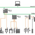
AS-Interface is a master-slave bus, with a single master controlling up to 62 slaves. It operates at the lowest level of the fieldbus hierarchy, but when implemented with an AS-I master/gateway (sometimes referred to as simply an AS-I gateway) it can connect to a higher-level network, such as DeviceNet, EtherNet/IP, PROFIBUS, or others.

Note that AS-I masters are also available for applications that don’t require gateway functionality. The AS-I masters simply connect to the higher-level control, such as a PLC, PC-based control, or DCS (distributed control system).

AS-Interface Layout
A basic layout of an AS-I network. Note that the addition of two repeaters allows the physical length of the network to be extended from the standard 100 m limit, up to 300 m.
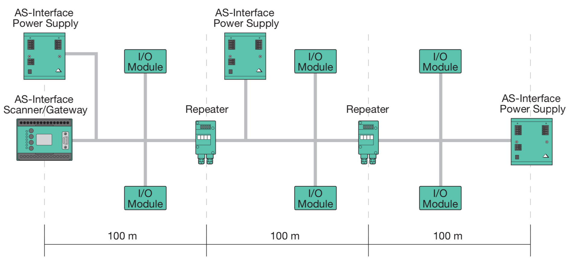
Image credit: Pepperl+Fuchs

The master/gateway manages communication with the slaves and communicates diagnostic information and faults to the higher-level controller or network. It polls each of the slaves in sequence and waits for a response (referred to as “cyclic polling.”) If a slave fails to respond, the master/gateway repeats the request, and if still no response is received, the master/gateway notes the slave’s address and sends this information to the higher level system.

AS-Interface master-slave communication
With extended addressing, each of the 31 addresses is used twice (1A/1B, 2A/2B…31A/31B) for a total of 62 addresses.
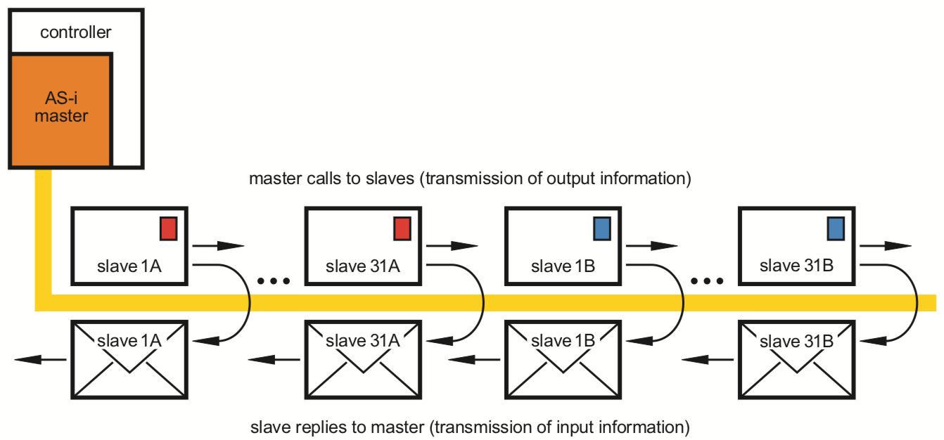
Image credit: ifm electronic

AS-Interface also offers safety functionality, referred to as “AS-I Safety at Work.” With the addition of a safety monitor, the AS-I network can manage safety devices such as e-stops, light curtains, and door latches, with compliance to safety standards SIL3/PLe.

The main benefits of AS-Interface are its simplicity, low cost, and high speed. Up to 62 AS-I slaves can be controlled by one master when the extended addressing system is used. And each slave can have 8 inputs and 8 outputs, for a total of 496 inputs and 496 outputs. With the standard addressing system and 31 slaves, the maximum response time is 5 ms per I/O point, and with extended addressing, maximum response time is 20 ms per I/O point (with 8 I/O per slave). AS-I also has the benefit of being inherently deterministic and repeatable, so response time is reliable.

AS-Interface Cable
Both data and power are carried on the standard AS-I cable, and insulation-piercing allows devices to be added anywhere along the cable length without terminations.
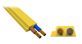
Image credit: Bihl-Wiedemann

Simplicity comes from the single, unshielded, 2-wire cable that transmits both power and data. Power is provided by a special AS-I power supply that also decouples power from data on the cable. If auxiliary power is required — for devices such as actuators — a separate cable (the same as the main power and data cable, but with a black jacket) can easily be added for a 24 V power supply. The maximum cable length as standard is 100 m, but lengths up to 600 m can be implemented by using repeaters and extension plugs. Connection to both the main cable and the black power cable is via insulation piercing, and slaves can be added anywhere along the cable and in any topology — line, ring, star, or tree. This provides significant flexibility and ease-of-use.


While AS-Interface was originally developed by a group of 11 companies who manufacture sensors, actuators, and control systems, it is a vendor-independent, open standard supported by IEC 62026-2 and the AS-Interface Association.

You may also like:

  • sensors
    Trends 2020: Sensors on the front lines of industrial networking

  • Motion-control systems help automate COVID-19 testing
  • star network topology
    What’s the difference between ring, star, and bus network configurations?
  • sensors
    What are IIoT sensors for motion systems?

  • What is IO-Link and how is it used in motion…

Filed Under: FAQs + basics, Featured, Fieldbuses, I/O, Networking + IoT

Reader Interactions

Leave a Reply Cancel reply

You must be logged in to post a comment.

Primary Sidebar

MOTION DESIGN GUIDES

“motion

“motion

“motion

“motion

“motion

POWER TRANSMISSION REFERENCE GUIDE

RSS Linear Motion Tips

  • Ride the wave of electrification: Off-highway designs with linear actuators
  • What are capacitive sensors and where are they used?
  • What factors contribute to air bearing stiffness?
  • Rails, screw assemblies boast 20,000 km travel without relubrication
  • When should you use a bronze lead screw nut?
Subscribe Today

RSS Featured White Papers

  • Identifying Best-Value Linear Motion Technologies
  • Learn how to reduce noise and distortion in encoders’ signals
  • Helical Planetary Gearboxes: Understanding The Tradeoffs
Tweets from https://twitter.com/Motion_Control/lists/motion-control-tweets

Footer

Motion Control Tips

DESIGN WORLD NETWORK

Design World Online
The Robot Report
Coupling Tips
Linear Motion Tips
Bearing Tips
Fastener Engineering

MOTION CONTROL TIPS

Subscribe to our newsletter
Advertise with us
Contact us
About us
Follow us on TwitterAdd us on FacebookAdd us on LinkedInAdd us on YouTubeAdd us on Instagram

Copyright © 2021 · WTWH Media LLC and its licensors. All rights reserved.
The material on this site may not be reproduced, distributed, transmitted, cached or otherwise used, except with the prior written permission of WTWH Media.

Privacy Policy | RSS