
Electronics are getting smaller and lighter. This is especially true in defense applications, where achieving high power density in small packages is almost always a given.
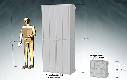
Moog’s Naval Business Unit was recently given such a challenge, as it needed to fit fifteen times the amount of power without increasing volume into a controller. By refining topologies, including using a novel fluid, Moog met the challenge and then some.
For some time, Moog has designed 10 kW peak sine drive controllers. To build on that, a team led by Jason D. Weiss, Engineering Manager and Emily Ceccarelli, Project Engineer, set out to develop a 150 kW peak controller. The team studied a variety of options to increase the power of that drive topology, focusing on four areas that predominately impact power density: reducing losses, high thermal conductivity, increased operating temperature and reduced package volume.
To reduce the losses within the controller, a trade study using silicone carbide (SiC) switching devices in a multilevel configuration was performed. SiC MOSFETs have proven to have lower conduction losses, lower switching losses and operate at higher temperatures when compared to silicon MOSFETs and Insulated Gate Bipolar Transistors or ICBTs. The team increased output voltage to approximately double that of the baseline design to help decrease the output current and reduce filter losses. Therefore, a multilevel configuration versus a standard inverter would provide for a reduction in voltage stress on the desired switching devices. The overall controller was designed for a system efficiency of 95%. And although they were able to increase efficiency, they still had to manage 7.5 kW of heat.
Various cooling and heat management methods were investigated including natural convection, forced air, liquid cooling and heat pipes. The team considered factors such as weight, heat transfer, conductivity, complexity, cost and feasibility. They found that the areas providing the most benefit for the application were water-cooling for managing external heat and Novec dielectric fluid to handle the internal heat.
According to Ceccarelli, Novec is a 3M-brand of environmentally friendly, inert fluid, which was “designed to boil at a specific temperature and allow the components to run at a specific heat.”
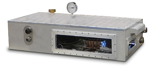
To obtain a better understanding of the dielectric fluid immersion along with the SiC devices, Moog engineers developed a test unit that could house high power resistors, inductors and the SiC devices along with its drive circuitry. The engineered dielectric fluid has a slightly higher conductivity than air, but the main heat transfer method of the fluid is phase changing—boiling from a liquid into a vapor. When a liquid boils it takes energy, called heat of vaporization, to change from a liquid to a gas. During this phase change the temperature of the liquid remains constant.
The second part of the two-phase cycle is condensing. All of the heat absorbed by the vapor rises with the vapor and must be transferred to the condenser for the phase change from vapor to liquid again. The liquid cold plate removes the heat from the enclosure to an external heat exchanger.
In the test, power resistors were placed at various orientations to understand different boiling affects. The resistors used for testing are rated for 260 W in a typical air-cooled heat sink-mounted arrangement. With the dielectric fluid, they obtained power levels close to four times the rated power of the devices without destroying the device.
The SiC Module circuit card along with the module was submerged in the Novec, but because the fluid has a dielectric constant that is nine times that of air, it appeared that surface currents hindered the system from running for long periods of time. Moog developed an inductor for the overall 150 kW design and tested that in the fluid as well but was unable to obtain boiling at 200 A of power, which was the supply limit. To further the investigation in the reduction of the inductor, they took a copper strip that was 4.5 x 0.5 x 0.0014 in. and performed the same test. This small piece of copper which would normally have vaporized in air well below the 200 A level ended up boiling the Novec and remaining at a stable temperature of 55°C. This information led to a reduction in size of the inductors and overall filter size.
Armed with this information from testing, Moog was able to develop a controller capable of handling fifteen times the amount of power and is smaller in volume by approximately 500 in3. The actual controller is only 18 x 18 x 8 in.
In addition to the benefit of submerging inductors in fluid, the team also saw a benefit in testing the dielectric fluid to help maintain extreme explosive arcs. As a result, the fuse industry could also benefit from using Novec fluid.
“I would love to see this design broken up into elements that would be retrofitted into whatever design application is needed whether it is extreme filtering for a wind power application, fuses to be used for a ground vehicle application or utilization of SiC modules in a commercial aircraft application,” Ceccerelli said. “My dream customer for this has always been the U.S. Navy. I have worked on various electronic designs for naval applications and would love to see this replace hydraulic designs that operate at various power levels.”
Weiss added that the controller would suit “any vehicle with something large and/or heavy that needs to move, be it a ship with a large rudder, a tank with a big turret, or an aircraft with very high force control surfaces. You can let your imagination run wild there I suppose, there’s really no limit to the places where there might be applications for this sort of thing.”
Moog, Space & Defense Group, Naval Systems Business Unit
www.moog.com
Leave a Reply
You must be logged in to post a comment.