
For applications primarily needing the holding of a load with little movement, there are special servo-motor sizing considerations. But confusion often arises from the terminology used to describe such designs — especially from the common use of the term stall in the servo-motor industry. Here we clarify the definition in context and then relate it to the axis’ effective RMS force-torque calculation for proper motor sizing.
By Hurley Gill • Senior applications and systems engineer | Kollmorgen
Expansion of closed-loop feedback systems into nontraditional servo-motor designs has prompted more demand for specialized motor functions. Some of these servo-motor applications require forces or torques to maintain a load for a time that’s quite long relative to the axis’ motion profile. This necessitates clarification of terminology — especially of terms that aren’t synonyms or only equivalent under specific operating conditions or events … but used interchangeably by those incorporating other motor types.
Potentially inconsistent communication can cause incorrect interpretations between parties and degrade motor sizing, machine programming, machine startup, and the troubleshooting of events or product-process issues.
For example, the terms stall or stall torque never appear in specifications for induction motors. But the terms are often used to describe conditions arising when load on the motor exceeds the full-load or breakdown torque capacity. Non-servo-motors (such as induction motors) in anything other than proper working condition are said to be in a locked-rotor or stalled (zero rpm) state. If an applied load exceeding the motor’s continuous full-load torque persists, the power demand will as well … and the motor will overheat and eventually burn up.
If a motor is stalling (0_rpm < actual rpm < full-load rpm) it draws a current greater than its continuous capacity … and if this condition persists, the motor’s windings will overheat. Such abnormal stall, stalled, or stalling conditions of an open-loop style induction motor aren’t a typical part of any normal application — so any induction motor under any one of these conditions is:
- affected by the motor’s ability to dissipate its heat losses relative to its load demand and
- will cause the motor’s windings to overheat and burn up if an overload continues.
A stalling motor may continue to run for a while at a slower-than-rated speed, but when it stops running (due to the tripping of an overload protection device or because it burned up) it is not stalled. After all, no unpowered or burned-up motor can recognize a mechanical load.
Servo motor designs — where a stopped condition might be by design
In contrast, the servo-controlled condition of purposefully holding position under a load (or maintaining a torque/force against a load) can be a normal function of a motion application … and one that’s completely different than our induction-motor example above. Unfortunately, it’s also a motor state that’s associated with and communicated by the terms stall, stalled, stalling, or locked rotor. So when a servo motor (being a closed-loop system) is properly sized for a specific operating condition, it will just do what it’s commanded to do and nothing else. When properly sized and operating normally (as sized) such a servo motor can handle its commanded load (to hold position under a load or maintain a torque/force against a load) within the defined event or motion profile — without threat of overheating.
In fact, most confusion in the servo-motor industry about these terms and their meanings stems from the fact that there’s no designated terminology to describe when a servo-motor is improperly sized or improperly used outside of its specifications. Describing such application issues with terms that should be reserved for open-loop systems generates confusion — mostly because of mixed interpretations and understandings of different styles of motor systems — such as open versus closed-loop control.
Because the terms in question are sometimes used interchangeably, let’s first describe how they’re used in the non-servo (induction) motor industry.
Significance of the locked-rotor expression for induction motors
For a powered open-loop induction motor, the term locked rotor is actually the condition or procedure for determining the maximum possible starting current (locked-rotor current or LRC) drawn by the motor while developing maximum starting torque (locked-rotor torque or LRT). This maximum starting current and its resulting maximum starting torque are typically measured in a lab environment with the motor’s rotor locked in place — hence the term locked rotor.
Locked-rotor current (LRC) is typically found on an induction motor’s nameplate identified as the locked-rotor amps (LRA), which is the maximum possible starting current drawn by the motor at zero speed when the power is first applied (and slip is at its maximum).
In actual induction-motor applications, this is the maximum possible current the motor can endure for a short (intermittent) period of time when power is first applied to the motor. That’s before the motor’s rotor accelerates to reduce slip (the Δrpm between armature field and rotor) to bring the motor up to a balanced operating point of equilibrium with the applied load — preferably within its continuous rating. Induction-motor open-loop intermittent currents exceeding the motor’s continuous capability are typically seen during acceleration (when power is first applied) and occasionally during process load disturbances … but overall root mean square (RMS) currents seen by the motor over time must remain within the motor’s continuous capability.
The performance of a servo motor (as that of other motors) is also affected by its ability to dissipate its heat losses — though it’s much less likely to overheat due to an overload than other motor types. That’s because servo controls and feedback along with closed-loop settings and limits from the drive amplifier (and potentially other controller programming) keep the motor within a safe operating range. Unlike the overload condition of an open-loop induction motor, the typical servo motor can be and is controlled to operate intermittently above its continuous capacity.
But just like the open-loop induction motor, the RMS currents seen by the servo motor over time must remain within the motor’s continuous capability. Otherwise, the motor’s windings will overheat. Intermittent overload states on a servo motor perform specific functions and are purposeful. So when these states are included in a design, engineers must account for them during motor-drive selection to ensure proper axis operation during normal machine operation, maintenance, safety events, and potential failures.
Servo-motor rating techniques used today were developed years ago — when most applications didn’t experience loading that was substantial (in relation to the application’s overall motion profile) during zero movement. So when one of these nontypical applications is under consideration, its requirements during these special conditions or events are evaluated separately. Results from this separate set of calculations may or may not override the application’s effective RMS torque calculation.
One specialized servo-motor use in robotic, industrial, and factory automation processes is to hold a specific torque/force against a load with little to no motor movement. The application may be as simple as a holding clamp or maintaining a vertical load against gravity (where a holding brake would increase process times or degrade precision) … or the application could be maintaining a torque/force against a load for testing … or dynamically holding a part in place for some process … or expelling a high-viscosity liquid in a controlled manner.
Among other things, a key element for sizing a servo-motor-drive combination for such use is the duration of this (effectively continuous) load with little to no actuator movement within its motion profile — or for some specific event — relative to:
- the motor and windings’ thermal time constants and
- the drive capabilities.
If the servo motor is properly sized and operating with proper drive-system settings for a given application, then it won’t overheat, trip a protection device, or burn up. Under such planned servo-motor utilization, the worst-case condition for the servo motor may actually be the motor’s continuous operation against its applied load (due to gravity or otherwise) during normal operation. Or the worst-case condition may be during a situation with a downed machine or line (or maintenance operation) that’s excessive in relation to calculated effective RMS torque/force requirement for the axis based on its motion profile.
Unlike an open-loop asynchronous induction motor (capable of sacrificing itself while trying to satisfy the needs of its load) a closed-loop servo motor’s torque, velocity, and position are controlled and limited by:
- the drive’s current/velocity/position loop gains and limits and
- the peak current limit of the drive’s foldback circuitry and programming over time — which is I2t foldback, typically set = Ic(motor) or Ic(drive).
Thus, even when the servo-motor may appear to be in a physically stalled or locked-rotor state, when properly sized and programmed, it is being specifically controlled within its continuous capacity and thus within the motor’s ability to dissipate its own heat losses. However, to describe this operation, especially when there is an axis issue, our subject words/terms are often communicated, with different meanings or interpretations in mind.
The servo-motor industry’s term stall often appears as a subscript on torque/force expressions and in other nomenclature to indicate a servo motor’s maximum obtainable continuous torque (Tc) and its resulting continuous current (Ic) requirement.
The continuous torque and its resulting Ic is at a specified ambient temperature (with an even steady-state heat-loss distribution throughout the motor windings) to deliver the torque capacity based on a specific temperature rise and heat sink (mounting plate) size — without overheating motor windings.
Such use of the term stall makes for a meaning that’s entirely different from the common definition of the word — in which stall means to stop and:
- when an induction motor can no longer move at its designed rpm against its applied load — with an appearance of a locked rotor (for a fully stalled or stopped condition) or
- stalling — on its way to be stopped — or
- stalling — running at an rpm that’s slower than rated, but not at zero rpm.
So it’s clear the word stall to describe induction-motor systems has a different meaning than stall used in the servo industry.
Widespread misconceptions about the term stall means that even some manufacturers’ publications incorrectly state that stall means zero rpm or no rotor movement.
Proper use of stall expressions for sizing ac brushless servo motors
Now the question is: How does one size an ac (brushless PM) servo motor so it won’t overheat at the windings — especially for designs needing continuous holding torque/force with little or no movement for a duration that makes the axis’ motion-profile effective-RMS calculation invalid?
As noted before, this invalidation is due to what would otherwise result in an uneven heat-loss distribution within the motor.
We’ll answer the question using an application example. First though, recall how manufacturer ratings for continuous current Ic(motor) are determined. We’ll assume RMS current with sine-wave commutation, but some manufacturers use other means to express Ic. Typically, servo motors are rated to establish maximum continuous capacity with heat distribution of internal winding losses that’s even throughout the motor. This means during the rating process, electrical cycles within the motor move at a speed fast enough to make for even distribution of heat due to internal losses … but slow enough to ensure jXL and core losses are essentially zero within the motor. This physical test speed is usually around 1 to 4_rps (revolutions per second) for motors but may be slower or higher — as a function of the motor’s pole pairs. Recall that jXL is inductive reactance.
Most manufacturers define continuous Torque (Tc) and resulting current (Ic) at this or similar speeds. The published continuous torque and current specifications are also often identified as stall torque (Tc_stall) and Stall current (Ic) regardless of the type of commutation and resulting current units.
Note the difference between stall as it’s used in the context of controlled closed-loop dyno tests (for determining a servo motor’s maximum continuous capability) versus our definitions for stall, stalled, and stalling as they describe overload conditions exceeding an induction motor’s maximum capability —whether the rotor has stopped moving or not.
Also consider what the servo drive’s output is doing, when a servo motor is held under some load with little or no movement. Because we are using sinusoidal commutation for our example, the controlled three-phase ac output is effectively at a standstill — presenting a continuously PWMed non-moving three-phase output with a value (appropriate to the servo motor’s commutation position) equal to what would essentially be a frozen signal at that position location. This may be envisioned in your mind’s eye as an instantaneous snapshot of the moving sine waves.
The main difference between the two major commutation methods is that:
Six-step or Block (unmodified trapezoidal) commutations only allows current flow through two of the three motor phases at any given time — for 2-ON 1-OFF at all times
Sine-wave or sinusoidal commutation allows for current flow through three motor phases at the same time (when appropriate) and each electrical cycle of the motor is presented as a sine-wave to the servo motor.
The two different commutation methods require a different representation of the motor’s torque constant (Kt). For more information, download a PDF white paper titled, AC Permanent Magnet and PMDC Brushless Servo Motor Parameters and Conversions and available at www.kollmorgen.com.
Most rotary servo-motor designs today have good thermal conductivity between motor windings, laminations, and frame — especially with epoxy encapsulation. That said, each design has a different thermal conductivity between windings and frame … and modeling those values accurately necessitates significant thermal modeling or actual measurements and testing. So for the purpose of this article, we’ll assume each motor winding is a standalone mounted coil — and that no coil sees a thermal advantage of transferring heat to the area of another winding or coil in the motor.
Under the condition of a fully loaded servo motor, the two worst-case commutation positions are:
- All (100%) current (I_actual = Ic x √2) going through one winding and 50% through the remaining two windings — as shown in Figure B
- All applicable (86.6%) current going through only two windings (I_actual = Ic x cos(30°) x √2) — as shown in Figure C.
These are the worst-case conditions the motor’s windings would see if the drive’s Ipk elapsed time (controlled by an I2t circuit/program) folds back to the motor’s published continuous current Ic_stall — established with the even heat-loss distribution of a slow rpm.
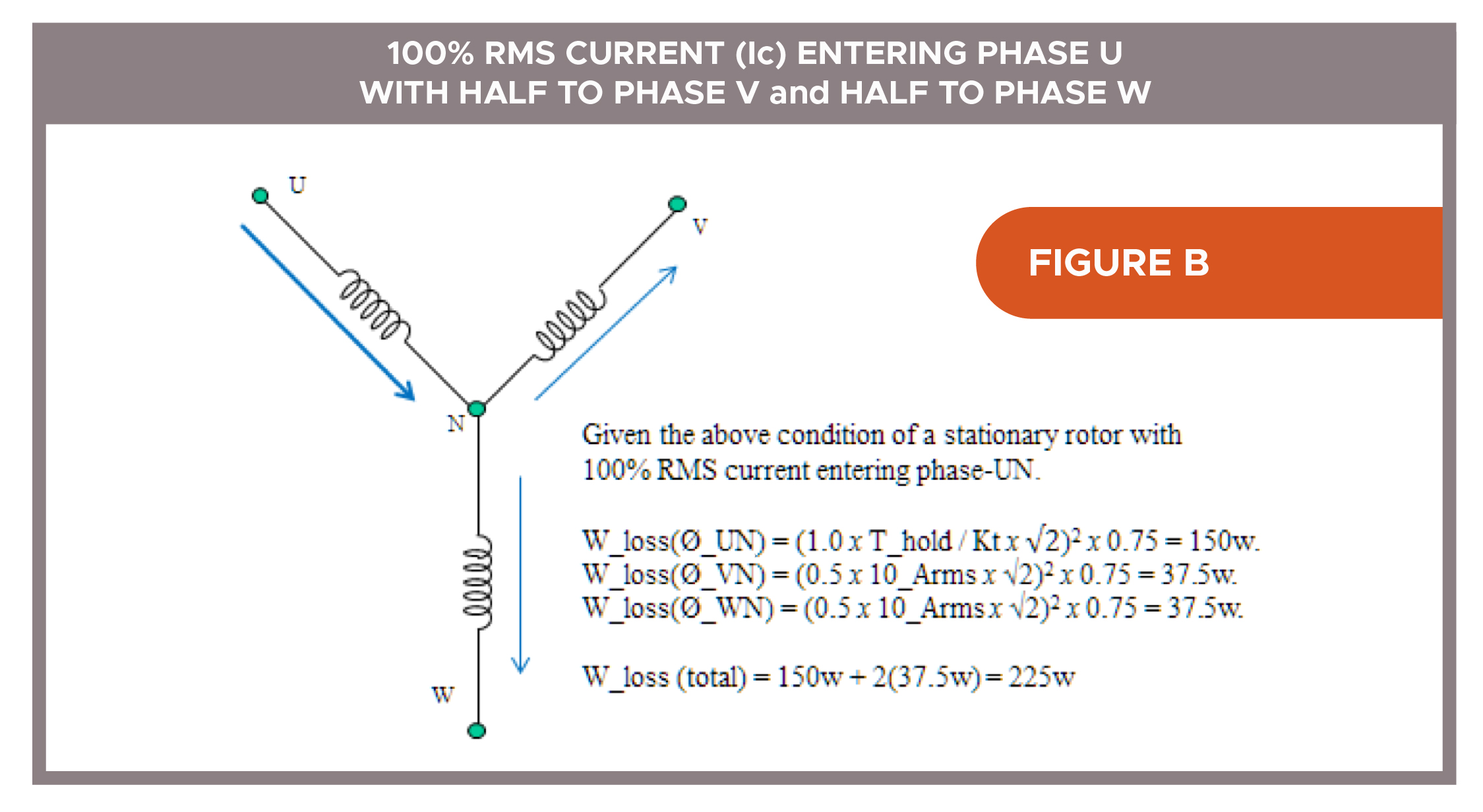
So for the condition shown in Figure B, assume Ic(motor)_stall = 10_Arms and a 10_Nm load. Also assume the commutation position and load necessitate 10_Arms through phase U to hold that stationary position. Then phase U actually has 14.14 DC-Amps [10_Arms x 2] continuously PWMed through it. That means the U winding must try to dissipate (14.142 x RmØ) watts-loss versus (102 x RmØ) watts-loss — twice its capacity — which of course it cannot continuously do.
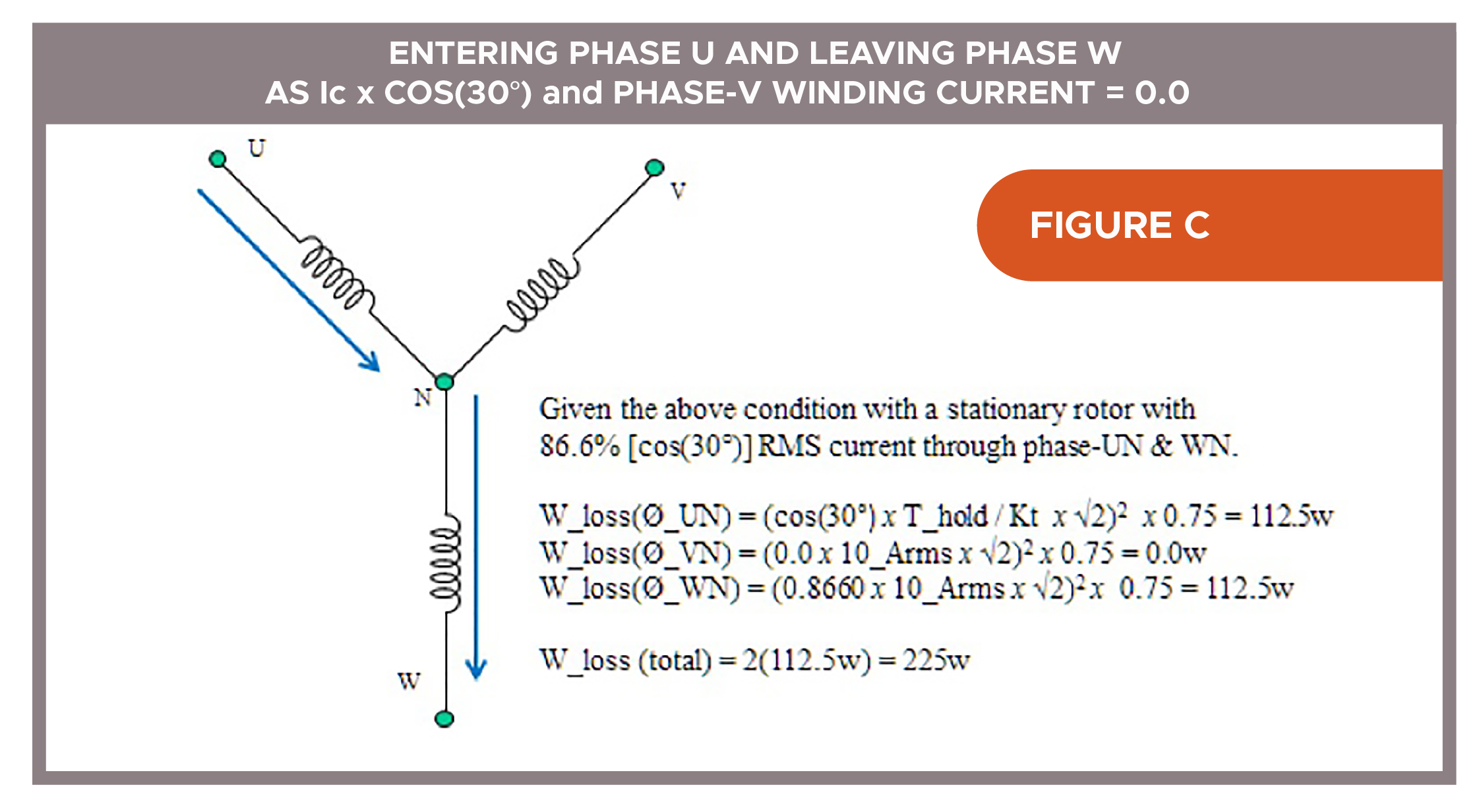
Similarly, for condition shown in Figure C, each of the two coils tries to dissipate (12.2472 x RmØ) watts-loss versus the (102 x RmØ) watts-loss — 50% over each coil’s capacity.
Calculations show it clearly — a critical factor when sizing a servo motor is the effectively stand-still current (to hold a load still) relative to the motor’s ability to dissipate its windings’ losses under such conditions.
So, we need a motor that has a continuous torque rating (Tc) equal to the √2 x T_hold required — not because we need any additional torque from the motor, but because we need each of the motor’s windings to reliably handle (for an effectively continuous period of time) what would otherwise be an instantaneous peak-crest of a moving sine-wave current.
Under these conditions (assuming nominal values and no margin) using a servo motor rated Tc (stall) = 10_Nm in an application requiring 10_Nm to indefinitely hold a vertical load is insufficient. However, choosing a slightly larger motor capable of a Tc (stall) => 14.14_Nm would be sufficient.
Additionally, if the drive is also rated in terms of Arms, it would only need to produce the continuous RMS current required to produce 10_Nm by the motor (approximately 10_Arms, if the servo motor’s Kt = 1_Nm/Arms).
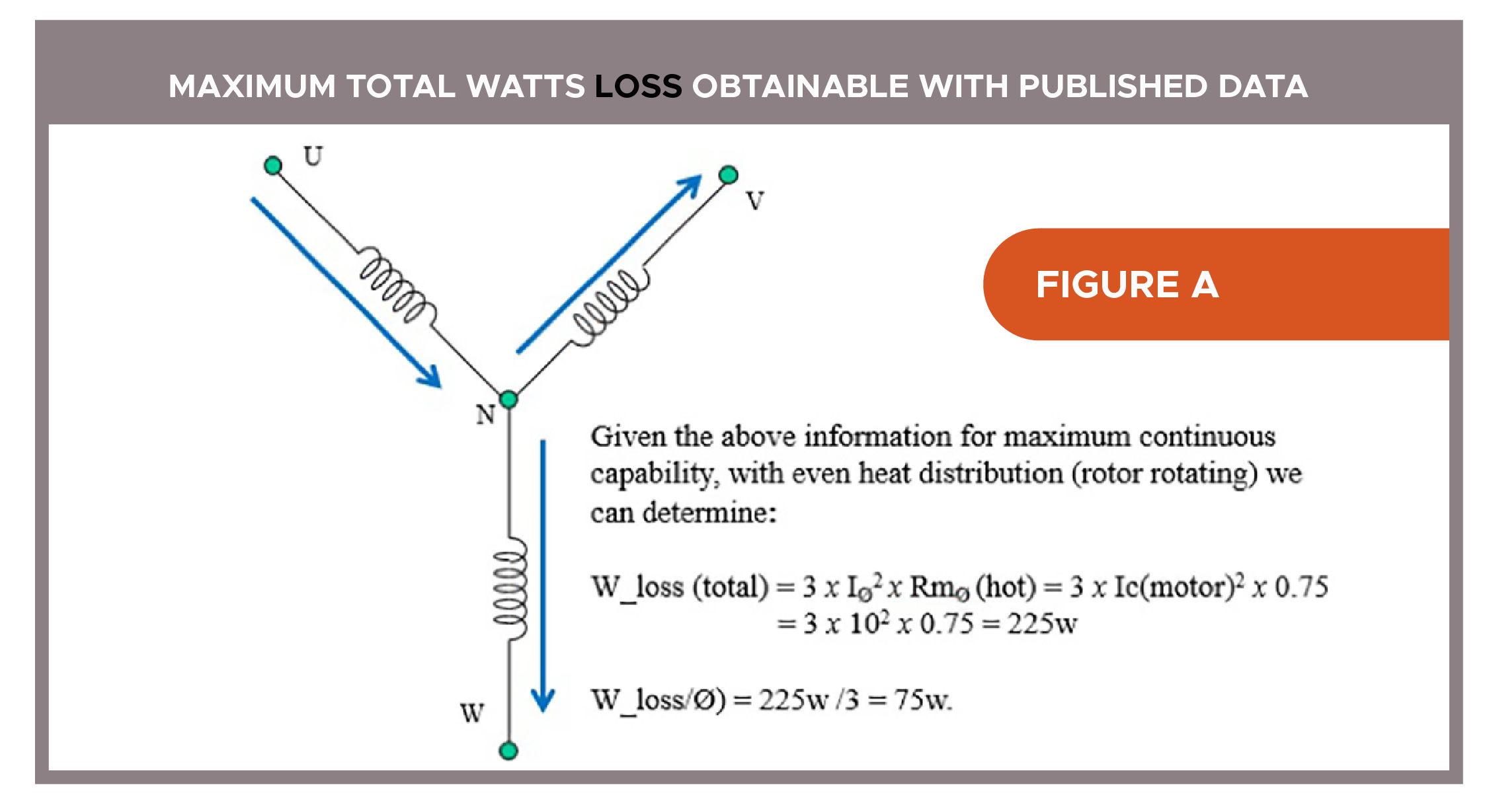
We can prove this by first determining the watts-loss capability at continuous rating — as shown in Figure A. Then we compare the wattage-dissipation capability against the two worst-case commutation points of the three-phase motor coils where current is 100%, 50%, 50% (Figure B) and 86.6%, 86.6%, 0% (Figure C).
Given the motor information:
Tc(stall) = 10_Nm
Ic(stall) = 10_Arms
Kt=1.0_Nm/Arms
Rm(L-L)_25°C = 1.006_ohms, where Rm(L-L)_150°C = (1.006_ohms x 1.491); and Rm Ø_150°C = 1.5/2 = 0.75_ohms
Temp (ultimate winding temperature for continuous operation) = 150°C
Temp-Rise (max. from a 25°C ambient) = 150°C – 25°C = 125°C
So based on this information, application conditions, and our assumption that each motor winding is a standalone phase (Ø) branch or coil (with no advantage of heat transfer to another winding’s thermal area) each winding can dissipate up to 75_watts.
If we consider the first of the two worst-case commutation positions with all (100%) current (I_actual = Ic x √2), we can conclude the watts-loss (total) will still equal 225_watts (Figure B); but the specific wattage needing to be dissipated through one winding (Ø_UN) is 100% over the previously calculated thermal capability of 75_watts (Figure A) and the other two windings are each at 50% capacity.
In this case (Figure B), to keep any of this motor’s windings from overheating due to this specific commutation position we would need to limit the Ic(drive) to 70.7% of the Ic(motor). For our example, if the given 10_Nm holding load requirement is maintained, this motor selection will NOT accomplish the job without overheating. Hence, a possible solution would be to select a motor with a capability: Tc => √2 x T_hold, preferably with about the same motor torque constant (Kt) so the maximum required application rpm may be maintained without changing the drive.
If we consider the second worst-case commutation position with all available (86.6%) current going through only two windings (I_actual = cos(30°) x Ic(motor) x √2) we see watts-loss (total) will again equal 225_watts (Figure C); but the specific wattage needing to be dissipated through windings (Ø_UN) and (Ø_WN) is 50% over the previously calculated thermal capability of 75_watts (Figure A) for each winding.
In this case (Figure C) we would only need to limit the RMS drive current (Ic(drive)) to 81.6% [100 x (75w/112.5w)1/2] of the Ic(motor) to keep the motor’s windings from overheating due to this specific commutation position. That yields a W_loss(Ø_UN) = W_loss(Ø_WN) = ((10_Arms / √1.5 x cos(30°)) x √2)2 x 0.75 = 75_watts.
Still, if the 10_Nm holding load requirement is not re-specified to a lower value, this motor selection won’t accomplish the job — as with the case depicted in Figure B. For this specific condition, we could select a motor with the capability Tc => √1.5 x T_hold. However, this still allows a 33.3% wattage overload of the first commutation condition as in Figure B.
A better solution is to select a motor with a capability Tc => √2 x T_hold as detailed in Figure B.
Understanding stall — for proper servo-motor calculations
Understanding the meaning of the term stall in a servo-motor context lets engineers correctly consider the specifics of an axis’ motion profile and load demands over relative load demand times (versus total cycle times). That way, dominant factors can be determined and analyzed for sizing calculations, machine-axis programming, and troubleshooting — for normal operation or otherwise. These dominant factors allow reasonable consideration between the results: RMS calculations and any effectively constant or constant, loads held for a long time relative to the axis’ total motion-profile time, the motor’s thermal time constants: TCT_motor and TCT_winding, and the servo drive’s I2t foldback algorithm.

Solid understanding of the motor’s worst-case commutation positions when holding a continuous load with effectively no movement (and standstill PWM drive commutation that comes with this condition) is core to proper motor and drive sizing. Holding a torque against a load (external or otherwise) for intervals that are long in relation to motion-profile times or thermal time constants can (if corrections aren’t made) make for erroneous RMS conclusions.
Side note: Similar considerations are required for intermittent torque requirements that are high relative to a motion profile’s times and demands and any proposed motor’s thermal time constants. This is a topic unto itself. Google Kollmorgen — Managing PM AC Servo-motor Overloads: Thermal Time Constant to download a white paper on this topic.
In real-world applications, the torque multiplier may be conservative considering the good thermal conductivity between today’s motor windings, laminations, and frame. Nevertheless, the author’s experience and collected feedback on motor designs and applications over many years suggests that the √2 multiplier for iron-core rotary servo motors imparts a safety margin of approximately 9 to 11%. Though this information has not been specifically verified, the worst-case scenario with the √2 multiplier seemingly offers enough margin to overcome typical manufacturing tolerances of ±10%. So selecting a motor with a continuous capability equal to the calculated continuous requirement (or slightly above) using the √2 torque multiplier is reasonable.

However, for ironless-core motors, no margin is assumed … and for these motors, design engineers are advised to specifically consider each manufacturer’s stall rating definition. The ac servo-motor industry’s stall is a limited term with a specific definition, but not so fixed that it couldn’t be redefined in part or in whole — especially for special-purpose servo-motors or those of a certain design — ac PM ironless-core servo motors, for example.
Kollmorgen | kollmorgen.com

Hurley Gill is Senior applications and systems engineer at Kollmorgen located in Radford, Va. He’s a 1978 Engineering Graduate of Virginia Tech who has been engaged in the motion control industry since 1980. He can be reached at hurley.gill@kollmorgen.com.
Since its founding in 1916, Kollmorgen’s innovative solutions have brought big ideas to life, kept the world safer, and improved peoples’ lives. Today, its world-class knowledge of motion systems and components, industry-leading quality, and deep expertise in linking and integrating standard and custom products continually delivers breakthrough motion solutions that are unmatched in performance, reliability, and ease-of-use. This gives machine builders around the world an irrefutable marketplace advantage and provides their customers with ultimate peace-of-mind.
For more information visit www.kollmorgen.com, email support@kollmorgen.com, or call (540) 633-3545.


Leave a Reply
You must be logged in to post a comment.