• Skip to primary navigation
  • Skip to main content
  • Skip to primary sidebar
  • Skip to footer

Motion Control Tips

Automation • Motion Control • Power Transmission

  • News
    • Industry News
    • Editor Blogs
    • Video
  • Controls
    • HMIs
    • PC-Based Controllers
    • PLCs + PACs
    • Stand-Alone Controllers
    • Software
  • Drives
    • Servo Drives
    • Stepper Drives
  • Encoders
    • Absolute Encoders
    • Incremental Encoders
    • Rotary Encoders
  • Mechanical
    • Bearings
    • Brakes + Clutches
    • Belt + chain
    • Couplings
    • Gears + Gearing
    • Lubrication
    • Shock + Vibration Mitigation
    • Springs + Rings + Seals
  • Linear
    • Actuators
    • Linear Motors
    • Linear Encoders
  • Motors
    • AC Motors
    • DC Motors
    • Brushless Motors
    • Gearmotors
    • Piezo Motors
    • Servo Motors
    • Stepper Motors
  • Systems
    • Conveyors + linear transport systems
    • Gantries + Stages
    • Rotary Tables
    • Grippers + End Effectors
    • Robotics
  • Networks
    • Connections + Sliprings
    • Fieldbuses
    • I/O
    • Sensors + Vision
  • FAQs
    • Motion Casebook
    • Motion Selection Guides
  • Suppliers
You are here: Home / FAQs + basics / FAQ: What are PLC function blocks and how does IEC 61131-3 classify them?

FAQ: What are PLC function blocks and how does IEC 61131-3 classify them?

September 23, 2016 By Miles Budimir Leave a Comment

According to the IEC 61131-3 standard, there is a difference between a function and a function block in PLC programming. The main difference involves internal memory. So for instance, a function can be described as something like an equation or formula that accepts inputs and calculates an output value. Moreover, it always returns the same output value for the same inputs. In contrast, a function block relies on internal memory. So it is possible to have a different output value with the same inputs because there is another value stored in memory that has an impact on the final output value.

Function blocks form the basis of the Function Block Diagram (FBD) PLC programming language, one of the five languages specified by the standard, the others being two textual languages [IL (Instruction List) and ST (Structured Text)] and three graphical languages, beside FBD including LD (Ladder Diagram) and SFC (Sequential Function Charts).

PLC function block diagram
A sample of a function block diagram showing typical function blocks connected together. (Image source: Wikipedia.)

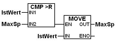
In FBD, function blocks describe the function between input and output variables. Inputs and outputs of blocks are connected together via connections or lines in the programming environment. The block represents some function or other; for example, it can be an elementary function such as MOVE or COMPARE, or a typical logic function like logical AND or logical OR.

The idea behind IEC 61131-3 was to have a vendor independent standard for PLC programming languages. The FBD language is structured as a logical sequence of functions, with the direction of execution being from left to right. Input values have to be generated before function block execution, and network evaluation isn’t finished unless all the output values are calculated.

More about function blocks and IEC 61131-3 standards can be found at the Open PLC website.

The ISA website also has information on IEC 61131-3.

You may also like:


  • PLC versus safety PLC

  • FAQ: Is a PLC fast enough to meet my application’s…
  • IDEC-Smart-relays
    Select the right machine controller for your application
  • Ultra-Packaging-Veronica-vertical-cartoner
    FAQ: Are PACs just for process control or do they…

Filed Under: FAQs + basics, PLCs + PACs

Reader Interactions

Leave a Reply

You must be logged in to post a comment.

Primary Sidebar

POWER TRANSMISSION REFERENCE GUIDE

DESIGN GUIDE LIBRARY

“motion
Subscribe Today

RSS Featured White Papers

  • Specifying electric rodless actuators: Ten tips for maximizing actuator life and system performance
  • The truth about actuator life: Screw drive survival
  • Top Ten Tips: How to specify electric rod-style actuators for optimal performance, reliability and efficiency

Footer

Motion Control Tips

DESIGN WORLD NETWORK

Design World Online
The Robot Report
Coupling Tips
Linear Motion Tips
Bearing Tips
Fastener Engineering.

MOTION CONTROL TIPS

Subscribe to our newsletter
Advertise with us
Contact us
About us
Follow us on TwitterAdd us on FacebookAdd us on LinkedInAdd us on YouTubeAdd us on Instagram

Copyright © 2022 · WTWH Media LLC and its licensors. All rights reserved.
The material on this site may not be reproduced, distributed, transmitted, cached or otherwise used, except with the prior written permission of WTWH Media.

Privacy Policy | RSS