• Skip to primary navigation
  • Skip to main content
  • Skip to primary sidebar
  • Skip to footer
  • Advertise
  • Subscribe

Motion Control Tips

Automation • Motion Control • Power Transmission

  • News
    • Industry News
    • Editor Blogs
  • Controls
    • HMIs
    • PC-Based Controllers
    • PLCs + PACs
    • Stand-Alone Controllers
    • Software
  • Drives
    • Servo Drives
    • Stepper Drives
  • Encoders
    • Absolute Encoders
    • Incremental Encoders
    • Rotary Encoders
  • Mechanical
    • Bearings
    • Brakes + Clutches
    • Belt + chain
    • Couplings
    • Gears + Gearing
    • Lubrication
    • Shock + Vibration Mitigation
    • Springs + Rings + Seals
  • Linear
    • Actuators
    • Linear Motors
    • Linear Encoders
  • Motors
    • AC Motors
    • DC Motors
    • Brushless Motors
    • Gearmotors
    • Piezo Motors
    • Servo Motors
    • Stepper Motors
  • Systems
    • Conveyors + linear transport systems
    • Gantries + Stages
    • Rotary Tables
    • Grippers + End Effectors
    • Robotics
  • Networks
    • Connections + Sliprings
    • Fieldbuses
    • I/O
    • Sensors + Vision
  • Resources
    • FAQs
      • Motion Casebook
      • Motion Selection Guides
    • Suppliers
    • Video
You are here: Home / FAQs + basics / FAQ: What are Hall effect sensors and what is their role in DC motors?

FAQ: What are Hall effect sensors and what is their role in DC motors?

January 11, 2017 By Danielle Collins Leave a Comment

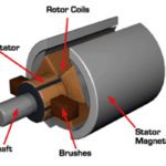
DC motors can be either brushed type, which are mechanically commutated, or brushless, which are commutated electrically. In brushless DC (BLDC) motors, Hall effect sensors are used in place of a mechanical commutator and brushes.

Hall effect sensors are solid-state, magnetic field sensors. They work on the principle that when a conductor with current flowing through it is placed in a magnetic field, the magnetic field induces a transverse (or sideways) force on the charge carriers, which pushes them to the sides of the conductor—negative to one side and positive to the other side. This buildup of charge on the sides of the conductor induces a voltage. This effect is referred to as the Hall effect, after its discoverer, Edwin Hall.

Hall effect sensors
A brushless DC motor with three Hall effect sensors to detect rotor position.
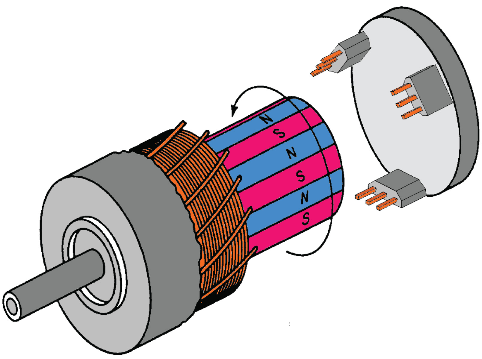
Image credit: Honeywell International Inc.

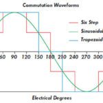
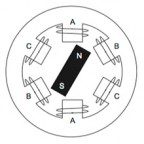
The purpose of commutation, whether by mechanical or by electrical means, is to energize the stator windings in a certain sequence, with one winding positive, one negative, and the third one powered off. Torque production is caused by the attraction and repulsion between the stator field and the permanent magnets of the rotor. Maximum torque is achieved when these two fields are oriented at 90 degrees to each other, and torque diminishes as they fields align. Therefore, in order to keep the motor turning, the stator’s magnetic field should change position as the rotor field “catches up” with it.

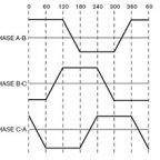
In order to energize the correct stator winding, the rotor position must be known. This is the job of the Hall effect sensors—to monitor the rotor’s position. BLDC motors typically have three Hall effect sensors mounted either to the stator or to the rotor, and use what is known as six-step commutation. When the rotor passes a sensor, it produces either a high or a low signal to indicate which rotor pole (N or S) has passed. This switching of the three hall effect sensors (from high to low or from low to high) provides rotor position information every 60 degrees.

Hall Effect Sensors
In six-step commutation, each of the three windings (U, V, W) is either energized positive, negative, or off, depending on whether each of the three Hall effect sensors has a high or a low state.
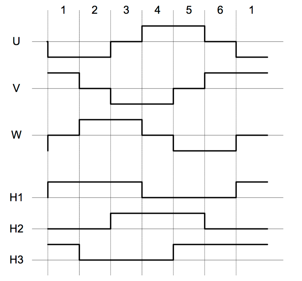
Image credit: Atmel Corp.

60° multiplied by six steps equals 360° or one full rotation. Hence, the term six-step commutation.


Hall effect sensors are the most common method of determining rotor position in BLDC motors, due to their low cost and ease of use with the permanent magnets of the rotor. And since the commutation happens in 60 degree increments, high-resolution sensing and output are unnecessary.

For a comprehensive but easy-to-follow tutorial on six-step commutation, check out this video from maxon motor.

You Might Also Like

Filed Under: DC Motors, FAQs + basics, Featured, Motion Casebook, Sensors + Vision

Reader Interactions

Leave a Reply

You must be logged in to post a comment.

Primary Sidebar

LEARNING CENTER

Design World Learning Center

Motion Control Handbook

“mct
EXPAND YOUR KNOWLEDGE AND STAY CONNECTED
Get the latest info on technologies, tools and strategies for Design Engineering Professionals.

RSS Featured White Papers

  • Robotic Automation is Indispensable for the Logistics Industry’s Continued Growth and Success
  • Reliable Linear Motion For Packaging Machines
  • Polymers Outperform Metals In Precision Gearing

Footer

Motion Control Tips

DESIGN WORLD NETWORK

Design World Online
The Robot Report
Coupling Tips
Linear Motion Tips
Bearing Tips
Fastener Engineering.
Wire and Cable Tips

MOTION CONTROL TIPS

Subscribe to our newsletter
Advertise with us
Contact us
About us

Copyright © 2025 · WTWH Media LLC and its licensors. All rights reserved.
The material on this site may not be reproduced, distributed, transmitted, cached or otherwise used, except with the prior written permission of WTWH Media.

Privacy Policy | RSS