
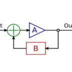
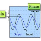
Gain is the ratio of output to input—a measure of the amplification of the input signal. A common example is the volume button on a stereo. This button controls the ratio of the input signal (received from the radio station) to the output signal (how loud the sound is from your speakers). When the volume is low, the sound is soft. This is low gain. When the volume is high, the sound is loud. This is high gain.
Servo systems are tuned using gains that help correct errors between the target value (position, velocity, or torque) and the actual value. The three primary gains used in servo tuning are known as proportional gain, integral gain, and derivative gain, and when they’re combined to minimize errors in the system, the algorithm is known as a PID loop. Another type of gain, referred to as “feed-forward,” can be used when the error is predictable, or when PID gains are insufficient to correct error and begin to cause instability or oscillations in the system.
PID gains
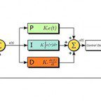
Proportional, integral, and derivative gains control how hard the servo tries to correct or reduce the error between the commanded and actual values. Using a PID loop is the most common method for servo tuning.
Proportional gain (Kp) is essentially a measure of system stiffness. It determines the amount of restoring force that should be applied to overcome position error. The term “proportional” is used because it is directly proportional to the amount of error. In other words, the error value is multiplied by the proportional gain to determine the controller output that will correct the error.
Integral gain (Ki) is related to static torque load on the system. The Ki value “pushes” the system to zero positioning error at the end of the move. This term is referred to as “integral” because it increases with time at the end of the move. The integral gain is multiplied by the sum of errors over time. Integral gain is not always needed, and is primarily used when the system experiences static loads.
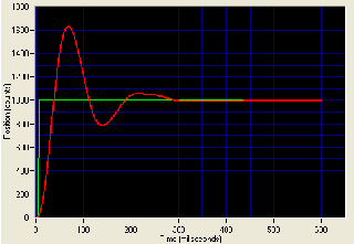
Derivative gain (Kd) represents the damping effects on the system, working with proportional gain to reduce overshoot and oscillations. The term “derivative” is used because this parameter is proportional to the rate of change (derivative) of the error.
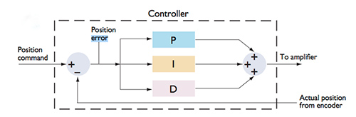
Image credit: Performance Motion Devices, Inc.
Feed-forward gains
Where PID gains are reactive—based on error that has already occurred—feed-forward gain is proactive. Feed-forward gains, which include velocity feed-forward and acceleration feed-forward, predict the commands needed to achieve zero error and inject them into the control loop.
Velocity feed-forward (Vff) works against viscous friction (friction that’s proportional to velocity) and minimizes error during the constant velocity portion of the move.
Acceleration feed-forward (Aff) works against inertia in the system to minimize error during the acceleration and deceleration phases of the move.
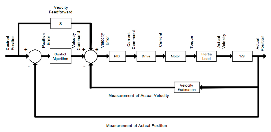
Image credit: Integrated Industrial Technologies, Inc.
Leave a Reply
You must be logged in to post a comment.