
The Swinburne test is an indirect method for determining the efficiency of DC motors. It works by finding the no-load losses experimentally and then estimating additional losses from the rated motor data. From this information, the efficiency can be determined at any applied load.
First, the no-load current and shunt field current are obtained directly via ammeters when running the motor with no load, at its rated speed and with the rated supply voltage. The no-load current is measured and denoted Io, and the shunt current is measured and denoted Ish.
Input voltage: V
No-load current: Io (obtained via measurement)
Shunt field current: Ish (obtained via measurement)
No-load input power to motor: Po = V*Io (1)
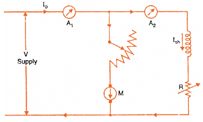
Image credit: studyelectrical.com
The no-load armature current is found by subtracting the shunt field current from the no-load supply current.
No-load armature current: Iao = Io – Ish (2)
Because the motor is running at no-load condition, the net output is zero. This means the input power is supplying only the losses, including:
- mechanical losses, including both friction and windage losses
- magnetic losses (aka core or iron losses)
- copper losses (aka I2R losses), including both armature and field copper losses.
Recall that the sum of mechanical losses and magnetic losses is referred to as the rotational losses.
The first losses to be calculated are the armature copper losses, based on armature no-load current and armature resistance.
Armature copper losses: Pa = Iao2*Ra (3)
Now we can determine the constant losses, Pc, which include the mechanical losses, magnetic losses, and field copper losses. The constant losses are found by subtracting the armature copper losses (equation 3) from the no-load input power (equation 1).
Constant losses: Pc = V*Io – Iao2*Ra (4)
With constant losses known, the efficiency of the motor can be calculated at any load.
Motor efficiency: ηm = output power / input power
Since output power equals input power minus losses, efficiency can also be written as:
Motor efficiency: ηm = (input power – losses) / input power (5)
The constant losses, Pc, were found above and do not change (hence the term “constant” losses). Armature losses, however, must be calculated for the applied load.
In order to obtain an accurate value of the armature losses under load, the armature current is multiplied by the loaded, or “hot,” resistance of the armature. To determine the “hot” resistance value, the resistance is measured at ambient temperature and multiplied by 1.17 for a 40° C temperature rise, or by 1.2 for a 50°C temperature rise. With the “hot” resistance known, the armature copper losses can be calculated.
Armature losses with applied load: Pa = Ia2*Ra
Armature current under load equals the load current, I (rather than no-load current, Io) minus the field shunt current. Therefore, armature losses can be rewritten as:
Armature losses with applied load: Pa = (I – Ish)2*Ra (6)
Efficiency can now be calculated using equation 5 for the motor with a load applied, based on input power (supplied voltage, V, times load current, I), armature losses with load (equation 6), and constant losses (equation 4).
Motor efficiency: ηm = (V*I – (I – Ish)2*Ra – Pc) / V*I
The Swinburne test is only applicable for motors where flux is virtually constant, which includes DC shunt and compound motors. The test does not work for series motors because they cannot be run at light loads, and because speed and flux vary significantly in series motors. And while this method provides a good estimate of motor efficiency, it doesn’t account for the change in iron losses from no-load to full load, or for stray losses in the motor. However, the Swinburne test is especially useful for large motors, where the power required to test motor efficiency directly would be significant.

Leave a Reply
You must be logged in to post a comment.