The following is an article from Elmo Motion Control that explains how some of their drives work and how that translates to better efficiency.
Machine builders always try to boost throughput while keeping a lid on costs. The best way to reach this goal is through the use of machine control capable of high dynamics and high-accuracy, generally employing a powerful servomotor and drive, along with a modern machine controller and precision mechanics.
All machine control involves the conversion of electrical power into mechanical power or work. However, the conversion process contains many sources of inefficiency. Inefficient power conversion is undesirable both because the machine consumes more power than necessary, and because numerous electrical-generation facilities in the U.S. still produce power by burning coal, a source of environmental pollution.
Elmo Motion Control helps minimize these effects and makes motion drives efficient through use of energy efficient techniques that include:
- Qualitative power
- A shared DC bus
- Stepping servo direct drive
First technique to make a motion system efficient: Get more qualitative power
Processes that are inefficient tend to convert a lot of the energy they use into heat rather than work. However, energy loss can also take other forms. For example, EMI, mechanical disturbances, and electrical instability are all forms of energy loss. Systems that experience these effects consume more power than systems where these effects are absent.
What is qualitative power for a servo system?
Qualitative power is the capability to deliver exactly the power required to the load. In other words, No less, no more.
Any difficulties in the mechanical transmission line connecting the power source and the mechanical load constitute sources of inefficiency. These difficulties can be viewed as sources of electrical and mechanical pollution:
• Parasitic and unwanted harmonics (electrical & mechanical)
• Excessive heat (in the drive, in the motor, in the mechanical load)
• EMI
• Mechanical vibrations and resonances
• Resonances (mechanical and electrical)
These effects essentially degrade the system’s performance.
The traditional remedies for these disturbances involve adding specific components, such as bulky line filters, line inductors, additional heat-sinks, and additional fans. In some cases, the mechanics require modification to become more resilient and more stable. In other cases, the operation may need to slow down to avoid vibrations and resonances.
The problem with such remedies is that they can inflate the machine’s size, add labor costs, and lose energy. Each added component is an addition source of energy dissipated as heat.
Components in the servo chain (load, motor, drive) all contribute to these inefficiencies.
Elmo’s approach recognizes that the servo drive dominates in reducing the overall pollution created by driving the load efficiently and thereby eliminating the need for compensating components of the servo chain. This approach improves performance, reduces costs and time-to-market, and contributes to producing a greener machine. Here’s the philosophy:
If you don’t create heat, there is no need to eliminate it.
If you don’t create noise, there is no need to eliminate it.
Use of smart advanced control eliminates the need to modify the mechanics.
Ideally, when a servo drive is commanded to drive a load, the drive responds by delivering the speed and torque to the mechanical load that is identical to that of the requested power in magnitude and timing.
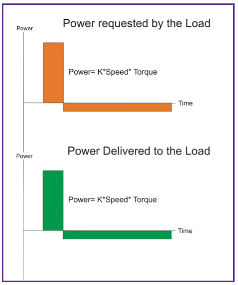
However, the actual power conversion is far from being ideal. It looks more like the plot below in green.
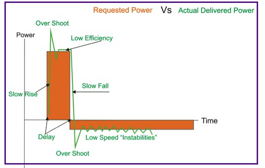
Typical parasitic effects of power conversion
To understand how inefficiencies can creep into servo operation, it helps to review the connection between power conversion and servo control. Dissipated power in a servo operation is:
Power = KP × Speed × Torque (or force)
where KP is a constant that depends on the units of speed and torque. From this relationship, qualitative power can be viewed as representing smooth operation of the servo components. The performance of the servo drive can be characterized by how efficiently the drive handles three “time domain” factors:
• Speed and position loops … the mechanical domain
• Torque or force performance … the electrical domain
• Power conversion … the PWM (pulse-width modulation) domain
Related to getting more qualitative power: Better PWM
PWM power conversion determines four factors characterizing servo operation:
1. Efficiency
2. EMI
3. Linearity
4. Response and bandwidth
Elmo’s proprietary power-conversion technology — fast and soft switching technology, or FASST — overcomes the drawbacks and limitation described above. Elmo’s newest Gold Twitter servo controller is a good example of a controller that also incorporates the requirements for a green servo drive. 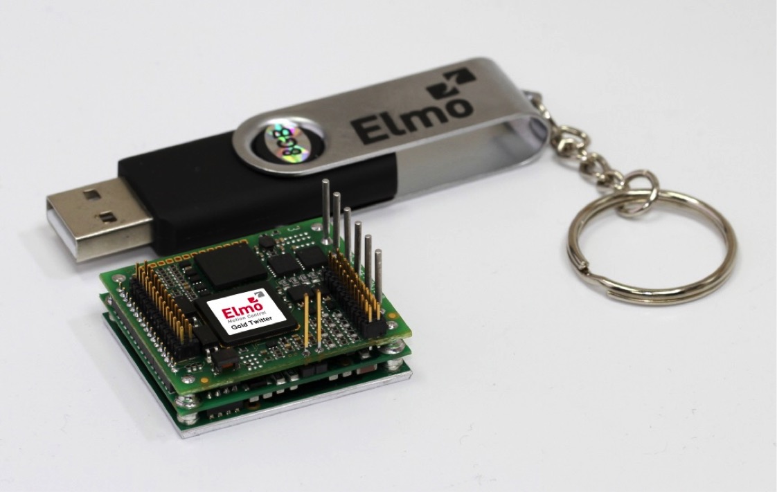 Gold Twitter is powerful, nano-sized, highly efficient, produces negligible EMI, and is small enough to mount nearly anywhere. Here’s what a performance drive does when controls turn it on:
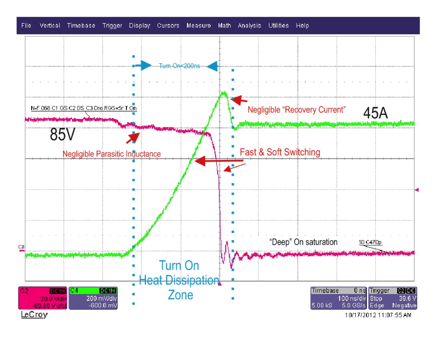 Perfect PWM on switching is fast (< 200 nsec), exhibits deep ON saturation, is highly efficient, and yet controls the turn-on process to minimize stress on electrical components and generate negligible EMI (very low recovery current).
Similarly, perfect PWM off switching is fast (< 100 nsec), has deep ON saturation, is efficient, and yet controls the turn-off waveform to put little stress on electrical components and generates negligible EMI (no voltage overshoots):
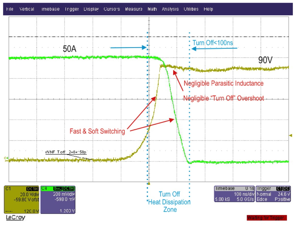
Elmo’s servo drives exhibit superior efficiency. For example, operating at 50 V and 50 A, Elmo’s drive dissipates ≈17 W, while competing drives specify 120-W dissipation for the same conditions. More specifically, the fast and smooth turn-ON and turn-OFF, deep ON saturation, negligible EMI, and smooth and linear transitions let the Gold Twitter:
- Deliver ≈ 4 kW with less thn 20 W dissipation losses
- Operate at a wider bandwidth and higher current (even at > 4.5 kHz) and speed … and give machines accurate positioning
- Provide faster and more precise response time
- Deliver exceptional wide current loop linearity … with a dynamic range of 2,000:1 (so a 50-A driver runs the motor smoothly and remains stable at 0.025 A)
- Implement a large assortment of advance control filters to meet any servo load requirements
Negligible EMI from nano drives
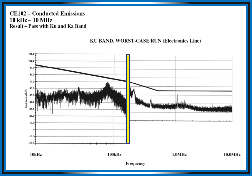 The result is a nano drive with tremendous power density. The Gold Twitter output power density is five to six times that of the Gold Hornet series. Until the release of the Gold Twitter, the Gold Hornet series was a world champion in output power density.
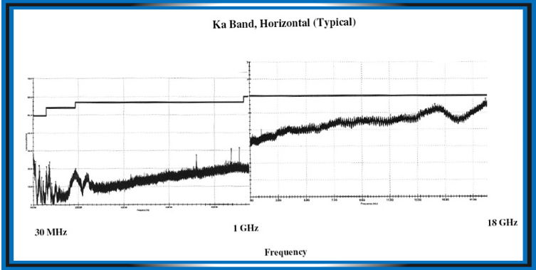
High efficiency and noise-free operation let the drive dissipate less heat — as there’s no need to reduce noise by external means.
Elmo drive electronics also fit in small volumes, so can mount on the moving load, on the motor, in the motor, or next to the motor. This close proximity minimizes cabling nightmares. Tip: Minimize cable runs in moving equipment, because specialized motion cables are expensive and can have a short life … and increase power consumption.
Torque and force control
Smooth, stable, fast response torque is essential not only for superior servo performance, but also to reduce power dissipated in unwanted electrical harmonics mechanical resonances. The quality of the torque is determined by two essential functions: Vector control and the current loop.
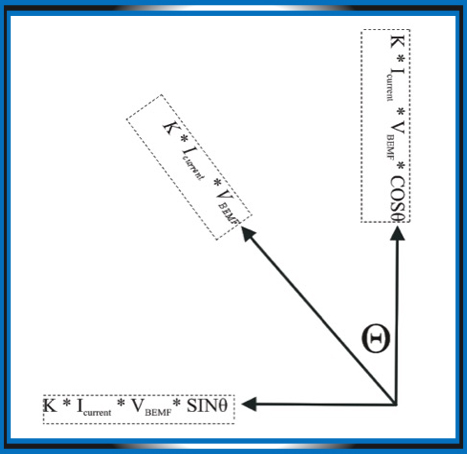
In a vector-control scheme, the torque (a vector) is:
Torque = K × Icurrent × VBEMF
= K (Icurrent VBEMF cos θ)+ K (Icurrent VBEMF Sine θ)
where VBEMF is the motor’s torque constant (equivalent to the back EMF voltage), and the servo drive creates Icurrent.
Only the K (Icurrent VBEMF cos θ) term creates a “real” torque.
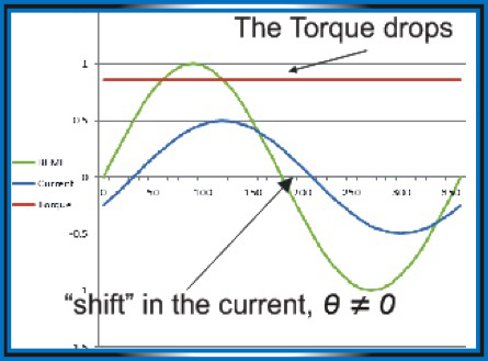
The K (Icurrent VBEMF Sine θ) term is “pure” torque degradation, comprised of heat losses and disturbances.
For high-quality torque, the Icurrent and the VBEMF must be as close as possible to a sinusoidal waveform.
The drive delivers a high-quality and efficient torque by striving for a few ideal conditions:
Maximum torque comes when θ = 0 (Cos θ = 1).
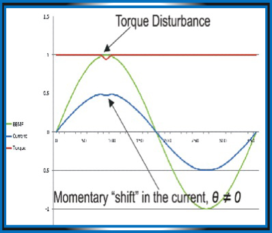
Smooth and stable torque comes when θ is constant and does not vary with time.
The vector control loop strives to create a sinusoidal Icurrent and keep θ = 0.
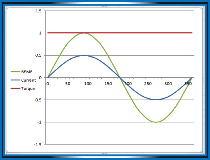 When Cos θ ≠ 1, the results are torque degradation, torque disturbances, and excessive heat.
A high-performance vector control scheme that fulfills Cos θ = 1 at any condition, with the right back EMF commutation, results in the highest torque that is smooth and stable.
Operating at this point also eliminates the need to force more current through the motor and consume more power to get the required torque.
Any operation at Cos θ ≠ 1 wastes energy and creates excessive heat.
Three servo-drive capabilities determine current-loop performance:
- Current-loop bandwidth
- Current-loop response time
- Current-loop dynamic range
The advanced and clean design of the power stage and current loop, operating in conjunction with EASII (Elmo’s Application Studio Software), enables a high-performance current loop and thus delivers exactly the required torque to the load. There is no need for additional power, no energy consuming overshoots and transients, and so on.
Velocity and position control
EASII, Elmo’s design-software tool, delivers optimal control of the mechanical load with negligible parasitic effects, thanks to its implementation of very wide bandwidth and high-precision current, velocity and position tuning. Here, Elmo’s philosophy is this:
We’ll get most out of your mechanics.
Elmo’s smart servo control often makes it possible to attenuate mechanical parasitic effects. So, it’s often possible to avoid expensive mechanical modifications that would otherwise be necessary to mitigate these conditions. The elimination of the mechanical parasitic contributes also to a greener solution.
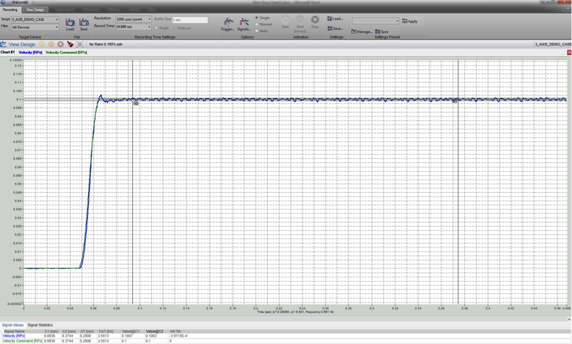
Here’s an example of fast, smooth, oscillation-free performance from Elmo’s servo drive with configuration and tuning handled by EASII (Elmo’s Application Studio):
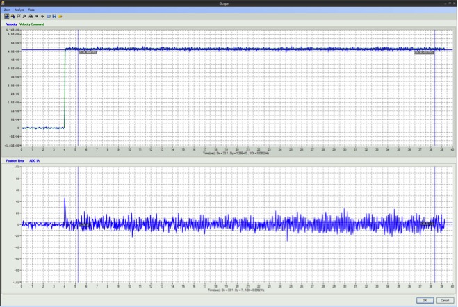
It imparts fast response; low overshoot; high resolution; and stable and oscillation-free operation.
How does Elmo deliver green power control?
- Wide bandwidth (current, velocity, position, vector) and fast response allows the required speed × torque/force (power) to be delivered/absorbed accurately and promptly.
- Vector control: Smart, precise, fast vector control results in smooth torque and power and eliminates inefficiency.
- An advanced tuning tool filters parasitic, non-linear effects (resonances, friction, inertia…), thus eliminating power pollution from the application.
- High-efficiency power conversion creates little need for additional power to overcome parasitic effects.
- FASST proprietary power switching results high linearity, fast response, world-class efficiency and negligible EMI – smooth servo operation with zero pollution.
Second technique to make a motion system efficient: Shared DC bus
Servos can operate in any of the four quadrants of the speed-torque plane:
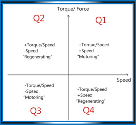
In Quadrants 1 and 3, the power is positive … meaning that power flows from the drive to the motor. The motor converts electrical power to mechanical power and uses it to move the load. This is the motoring operation.
In Quadrants 2 and 4 the power is negative. This means that power flows from the mechanical load back to the motor … so load inertia turns the motor shaft. Within the motor, mechanical power gets converted to electrical power and then is delivered back to the drive. This is power regeneration, sometimes also called braking.
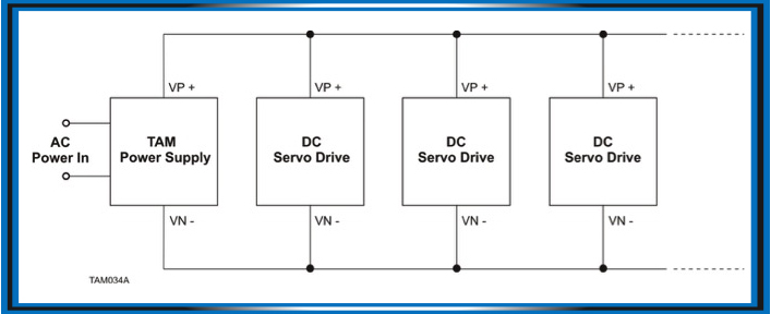
There are two basic topologies to power servo drives when operating from an AC source or network. The first is a shared DC power bus topology where a single power supply is used for powering multiple servo drives.
Shared DC power bus topology
AC common power bus topology
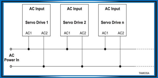
In the AC common power bus a separate power supply handles each servo drive.
Servo drive motoring AC power input
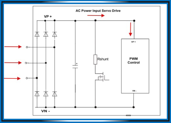
In AC power input servo drives, power flows from the mains to the power conversion stage during motoring.
Servo drive — regenerating AC power input
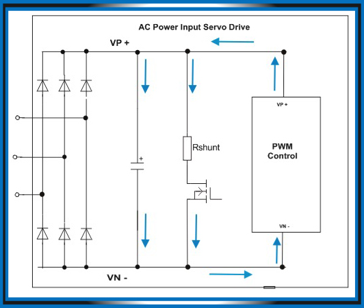
During regeneration (braking), the power flows from the power stage back to the DC bus in AC power input servo drives.
Power in the reverse direction charges the bus capacitance up to a certain trip voltage. Then a shunt turns on and dissipates the reverse energy flow. No energy flows from the mains.
Servo drives — Motoring and regenerating AC power input
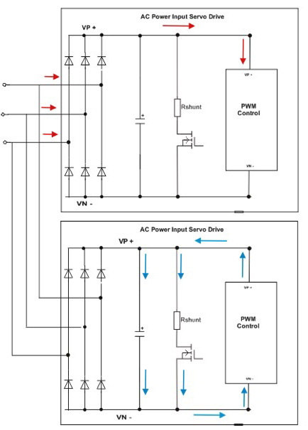
One of these AC input servo drives motors and consumes power from the mains. The other is regenerating and dissipating the reverse power internally. The reverse power can reach 2% of the total consumed power in advanced machinery with low friction, a high rate of acceleration and declaration, and a big moving mass.
In a DC shared bus, all drives connect to the same DC bus. The regenerating reverse power is used for motoring the other axis.
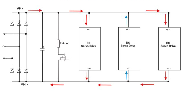
The benefits are:
1. No need to dissipate the reverse power internally.
2. No heat to expel from the drive, thus no need for additional cooling in the form of heat sinks, fans, etc. Note: The heat dissipated by a typical shunt operation is usually much higher than the heat dissipated by a PWM bridge.
3. Less power consumed from the mains
4. Less AC power gets rectified into DC voltage. AC rectification is a significant source of heat and reduces efficiency dramatically.
5. The energy saving in a multi-axis machine can exceed 5%. In extreme cases such as tension control (winding- unwinding machines) the saving can reach exceed 80%.
Note that Elmo’s Tambourine (TAM) is a compact shared DC bus power supply designed to power multiple servo drives.
What is a power supply for servo drives?
The nature of servo operation requires specific qualities from the power source. In most cases, the source is an AC line, single or three phases, wired either directly to the mains or via an isolation transformer. Servo operation requires a voltage source that is reliable, simple, capable of delivering momentary high power demands, and which conducts power from and to the motor (in four quadrants of operation).
In addition, the power supply must withstand a hostile operating environment: Voltage instabilities, high spikes, transients, bursts, EMI, high mechanical vibrations and mechanical shocks, extreme temperature, high humidity, and so on.
The Elmo TAM meets these specific tough requirements, and has two major tasks: Supply the DC bus voltage needed to power the servo drives and absorb the regeneration or braking power from the motor and mechanical load
To do this, the TAM:
• Rectifies the AC voltage input into a DC bus voltage; acts as a bi-directional energy reservoir for the servo system’s continuous and instant peak power demands.
• Acts as a shunt regulator for absorbing energy from the load during regeneration or braking; acts as an inrush-current limiter
• Acts as a high-frequency current ripple or swallower; filters EMI from and to the servo drives
• Provides line-voltage transient protection; and provides a measure of safety
Simplified schematic of a power supply for servo drives
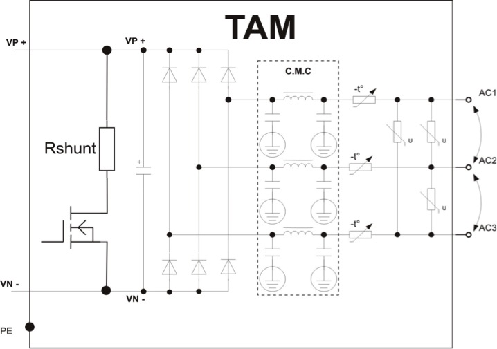
Advantages of the shared DC power bus
Sharing resources — A typical servo consumes peak power during its numerous accelerations decelerations. Typically these periods are relatively brief. The average power the servo requires is significantly lower. In the AC common power bus each section of the servo drive’s power supply must be designed to deliver peak power. In contrast, the shared DC power bus has a ratio of averag or total instantaneous power consumption that is much lower.
A great advantage of the shared DC approach is the shared shunt regulator. Servo operation is characterized by short and sharp braking or direction changes. It is rare that all drives regenerate energy simultaneously back to the DC bus. So one shared shunt regulator can serve a number of servo drives simultaneously. In contrast, with the AC common supply, each shunt regulator must be large enough to absorb the regeneration energy of the motor and it cannot be supported by the neighborhood shunts. Therefore, there is a large waste of duplicate shunt regulators.
In many servo applications while one servo brakes, the others motor (consume power from the supply). Sharing one DC bus allows energy to flow from the braking drive to the motoring drives without activating the shunt regulator. This eliminates the considerable heat dissipation required in regeneration. For cases of a winding – unwinding application, the technique can save over 80% of power that would otherwise be consumed.
Eliminating the need for duplicity — Any power supply connected to an AC source requires the same internal functions: A rectifying bridge, voltage suppressor, inrush current limiter, EMI circuit, shunt regulator, and capacitance.
A shared DC power bus (TAM network) needs only one set of these components. In the “AC common power bus, each drive must have all of these components.
Fewer electrical components — Safety regulations require that each load connected to the mains must have a protection element in series.
Thus, on the AC side, each element connected to the AC must contain at least a circuit breaker. In many cases, a contactor is also required to operate the machine safely.
The direct-drive approach
Most standard servo motors are designed to rotate from 1,500 to 3,000 RPM. In many cases the maximum application speed is much lower. There are two major means to adjust the maximum application speed, through a mechanical reducer (gear), or through use of a direct drive servo motor.
The use of a mechanical reducer adds a mechanical stage to the transmission line, reducing the life time of the motor-gear unit. It also adds inaccuracy (backlash) to the system, raises cost, and reduces efficiency. A single-stage reducer (reduction up to 10:1) has ≈ 80% efficiency (high-quality reducers reach close to 90%).
The use of a direct-drive servo motor is a high-performance solution, but the cost is high and in many cases, unaffordable.
Elmo offers a direct drive that’s affordable. It includes:
- A standard stepper motor
- High-resolution encoder
- High-performance stepper servo drive
The cost of a stepper direct drive solution can be 50% to 60% of that for a conventional direct drive servo. This cost difference can make it economical to migrate to direct drive from a system employing a reducer, while also eliminating energy losses. Elmo’s stepper servo drive is available in sizes up to 20 Nm.
Third technique to make a motion system efficient: Direct drive in the form of a stepping servo
Elmo combines the advantages of a low-cost standard stepper motor with those of a direct drive. A low-cost microstepping motor operating in a closed control-loop architecture replaces an expensive direct drive motor, without losing any motion performance.
In one example, this approach demonstrates high-accuracy motion positioning and speed by rotating an unbalanced load with a controlled torque, turning accurately even at ultra-slow rotational speeds:
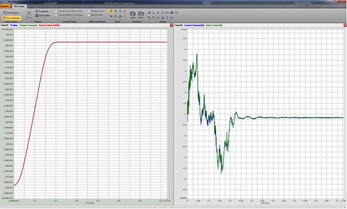
A signal-conditioning algorithm makes performance fast and precise during move-and-settle motions of an unbalanced changing load, without vibrations. This behavior enables a high holding torque at stall and at ultra-slow speeds. Use of advanced scheduled and fixed filters, gain scheduling, and other high- end control capabilities overcomes the influence of mechanical defects. The system eliminates the cogging effect by applying several methods of compensations.
The high-performance servo control which is a standard capability in all Elmo Gold series drives is a key element of this solution.
- High current dynamic range resolution (1:1,000 ratio)
- High sampling rates of up to 60 μsec for the three servo control loops (1:1:1 – 60 μsec for position, velocity and current)
- High control bandwidths as normally required for current and velocity loops
- Special gain scheduling methods for fast and smooth settling
- Large number of scheduled and non-scheduled bi-quad high-order filters that can be placed in almost any link of the servo control loop
- Special algorithms such as signal conditioning (Figure 3) for fast move and settle motions without vibrations
- Nonlinear compensation methods
Fast move and settle system response
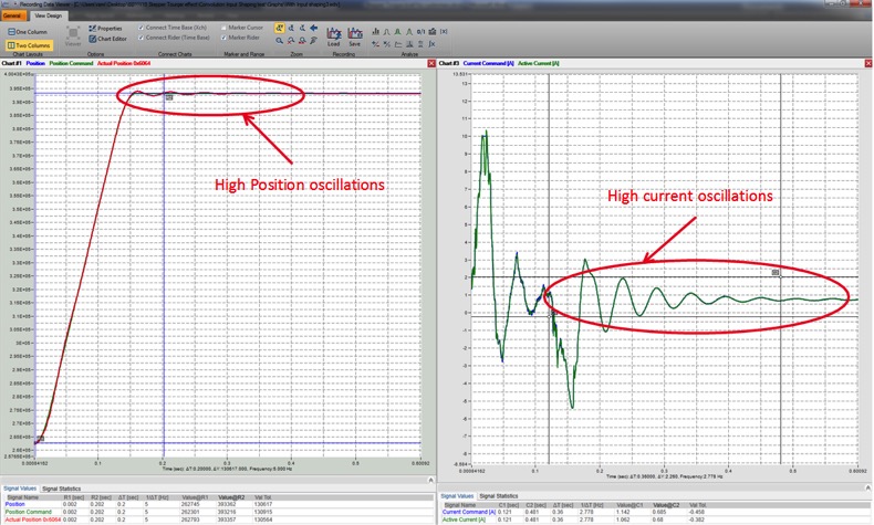
Fast move and settle using signal conditioning algorithm
One demonstration
An unbalanced stainless steel load of 500 gm is directly coupled to a stepper motor shaft via a metal rod. Advanced closed-loop servo control capabilities maintain accurate ultra-slow rotational speeds while the load weight changes as a function of the rod rotational angle. A 20-bit absolute serial encoder allows high positioning accuracy and precise rod motion at low speeds. The rotational rod angle changes as a function of the rod rotational speed.
High-bandwidth current and velocity control loops make possible precise motion speeds as lower as 0.01 RPS (rotation per second). At 0 and 180ᵒ (vertical rod orientation) the external torque is zero, while at 90 and 270ᵒ (horizontal rod orientation) the external torque is at its maximum. Between those angles the external torque changes as a function of the rod length, mass of the weight, gravity (9.81 m/sec2) and sinusoidal function of the rotating rod angle.
Other application examples
Requirements for machine-tool productivity, accuracy and dynamic performance have risen in recent years. Direct-drive technology has emerged as a good way to meet these demands. More specifically, the combination of a low-cost stepper motor and advanced servo control significantly improves machine tool performance. Plus, Elmo drives and stepper motors can reduce machine cost, simplify machine design, and reduce maintenance.
Operating stepper motors as direct drives eliminates the need for gearboxes or any other mechanical transmission elements and enables a direct coupling of the payload to the drive. The motor can then drive the load with high dynamic response without backlash.
The relatively large number of magnetic pole-pairs in a typical stepper motor lets it produce high torque at stall, gives it a high dynamic stiffness, and also lets the motor undergo smooth velocity regulation with very low ripple. The benefits of a stepper motor are only realized if the machine tool is built to the necessary standards of precision and tension, and if the system incorporates a high-performance servo control.
In semiconductor wafer inspection and related applications, the direct coupling of motorized rotation stages brings reliability and high precision, plus an ultra-low profile. Direct-drive technology eliminates the worm gears of traditional rotation stages, providing a wide range of rotation speeds, superior reliability, and enhanced position sensitivity. Other applications that can benefit from these qualities include precision metrology, micro-robotics, drilling, CNC machines, packaging equipment, and more.
Other examples of suitable application areas include azimuth or elevation control, radar, pattern tracing and similar systems. High precision and accuracy at low tracking speeds are all essential for the proper operation of such high-end systems.


Leave a Reply
You must be logged in to post a comment.