
There are key differences between fixed-position indexing tables and closed-loop position indexing tables. Here we review them and how to control for maximum accuracy.
By Ken Pfahl, Sales Manager | Motion Index Drives
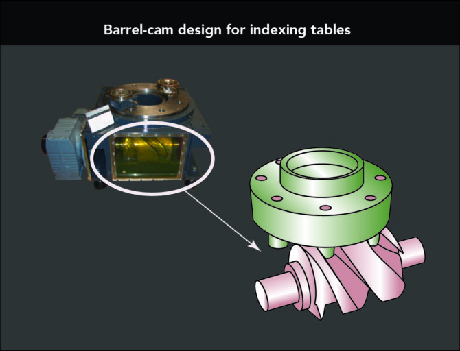
Indexing tables come in an array of versions with different speed and dwell settings to satisfy tasks in machine-tool handling, stamping, medical-device assembly, and bottle capping. These tables use mechanical drives, variable frequency drives (VFDs), programmable servo setups, and direct drives. Some mechanical cam-based indexers convert input into intermittent output by transmitting motion through a precision barrel cam. Versions that work as fixed-position indexers have the motion profile cut directly into the cam for engaging followers. Such mechanical drives are often simpler and more robust for set tasks than other options. That said, some indexing tables now integrate VFDs and even servos to deliver the intermittent movements of indexing with more flexibility where production requires it.
History of indexer controls and today’s leading designs
Legacy indexer designs include motor contactors and two-speed motors for control. There’s a good reason that two-speed motors were once so common. That’s because traditional indexers need to recover from out-of-position conditions at low speed due to the steeper angle cut into the cam and shearing threshold of the cam followers.
Fast-forward to today’s options. Now that VFDs are more affordable than before, they’re the first choice to get the same recovery from out-of-position conditions as that from legacy indexer setups. No wonder then that use of motor contactors has largely faded from existence as a method of controlling indexers.
In fact, the migration to VFDs has made it possible to use inverter-duty single-speed ac motors that accept VFD-based control. This enables more versatile indexing functions from constant-lead-cut cams thanks to closed-loop positioning. Such flexible systems differ from fixed-position indexers because (as mentioned) fixed-position indexers have the whole motion profile cut directly into the cam. In contrast, newer closed-loop positioning indexers use a VFD to control the motion profile. One caveat: While this is a more flexible setup, it’s also easier to incorrectly program such indexers … and even damage the cam followers and cam in the process. These are considerations when choosing the most suitable design for an application needing indexing …
| Consideration | Fixed-position indexer | Closed-loop position indexer |
| Accuracy | This is an extremely accurate and repeatable system, because the cam followers are preloaded against the cam (with cam perpendicular to the rotation). There’s no added cost for encoder feedback. | These indexers get even greater accuracies than fixed-position types because more preloaded cam followers always engage the cam. One caveat: Encoder placement and resolution can affect resulting accuracies and cost. |
| Capacity | This is a strong system using only two cam followers during the motion and when in the fixed position. | This is the leading system because more cam followers always engage the cam. |
| Complexity | This is the simplest indexer type. Engineers can use a lower-cost VFD and single sensor for recovering from out-of-position conditions. Entry-level controls engineers can configure these, too. | Closed-loop position indexers are more complex than fixed-position types in that the drive must be tuned and parameters must be set to correctly control the motion profile. Usually only an upper-level controls engineer can complete the setup. |
| Cost | This can be the most cost-effective indexer, but remember that there are many factors that affect cost. That said, this is usually the most cost-effective option where mass moment of inertia is low or index time is slow. | This usually has a higher cost of integration, because the design needs a more sophisticated VFD (able to handle encoder feedback). This indexer’s controls can only be setup by highly skilled personnel. Its encoders are costlier than the switches of simpler indexers, but the ability to handle much high mass moments of inertia can sometimes offset these additional costs. |
| Flexibility | This system is less flexible than closed-loop position systems. The number of stopping positions are pre-determined and are not cost effective to change. | This indexer is more flexible than fixed-position types because it allows for infinite number of stop positions. Remember too that the number of useable stop positions for typical applications are usually possible with a fixed-position indexer. |
Note that there are other options besides pairing ac motors with encoders for flexible indexer performance. Servomotors and amplifiers can also control indexers with closed-loop positioning. Such servo setups for indexers are the most difficult to commission, because most servo amplifiers used here are primarily designed to control robots … and so are limited by the restricted ways in which robot manufacturers allow control of auxiliary motors. What’s more, many of these designs don’t allow for modified trapezoidal motion profiles, either — so the design is forced to have rates of acceleration and deceleration that are identical. This limits indexer sizing due to the inability to create balanced motion profiles that properly limit torque into the indexer.
More details on fixed-position indexing tables
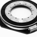
Cam-based setups that run at constant speed convert constant input-drive motion (from a motor) into intermittent motion output through mechanical means. Indexer-part manufacturers digitally shape the cam upfront so it doesn’t cause jerk but instead makes soft and shockproof strokes optimized for the task at hand. Most such cams go into assemblies to maintain secure mounting to the output table (sometimes called a dial). The motor is usually a three-phase brake motor that transmits power through a chain wheel, belt wheel, or gear reducer to the table driveshaft. This connects directly to the barrel cam to turn cam followers and output flange. The flange sits inside a wire-bearing assembly free of backlash, and the whole drive is sealed against ingress.
Some versions include flame-hardened cams and followers for smooth acceleration and deceleration as well as robust endurance in extreme environments. Accuracies to ±0.008 mm are standard with myriad configurations. One option is a locking dwell to get standalone precision for critical stations. Other choices include a reinforced output-flange bearing for higher tilting moment; an optional friction clutch on the drive; and dwell and step angle tailored to specific requirements.
Options for flexible and programmable indexing tables
As mentioned, flexible indexer designs use either a servomotor setup or an ac-motor setup with an encoder. Indexing tables that run off a VFD can cycle the motor driving the cam at a preset speed to a preset dwell and then stop. That lets the dial park at a location for seconds to hours — to allow processes at a station to complete before advancing a workpiece to the next station, for example. The encoder tracks camshaft position for high positioning accuracy. Some designs have the output dial ride a high-precision four-point bearing assembly preloaded against runout. Some manufacturers seal the whole drive against dust and moisture ingress.
The drawbacks of the other flexible indexer setup — that based on programmable servos — have already been mentioned. But to address a major issue for applications that need the highest level of programmability, some manufacturers design their servo-based programmable index tables so they’re identifiable by all robot brands and controls.

Note that cams provide mechanical benefits even in these forms that rely on controls for some motion profiling. Consider how these indexer setups have a gear reducer that connects the motor to the barrel cam’s input shaft, but the barrel cam rotates the top dial through cam followers with a rigid zero-backlash connection. This direct connection between the table’s rotating dial and cam eliminates the focus during design sizing on toque output for geared linkages. Instead, the machine builder can work with the manufacturer to size the cam drive to the total system and payload moment of inertia. That ensures the kinematic assembly of the indexing table withstands the application’s inertia loads without issue.
Final consideration: Stopping indexers during emergencies
Note that one of the most important aspects of controlling indexers is handling emergency stops. Fixed-positioned indexers use a brake on the motor sized to stop the load’s mass moment of inertia. In contrast, closed-loop positioning indexers always have a brake attached to the motor for maximum holding power. But this type of braking almost always stops the indexer faster than the capacity of the indexer, so must not be used in emergency-stop situations. Instead, closed-loop positioning indexers must have emergency-stop procedures that use the motor controller to stop the load.
Contact the author at kp1@mid.us.com or (248) 743-9999. Also visit Motion Index Drives at motionindexdrives.com.

Leave a Reply
You must be logged in to post a comment.