
Any machine that uses a VFD is subject to the effects of the drive’s chopped dc square-wave output signals. Here we explain how those signals affect and interact with motors and surrounding equipment, and how cables can help protect many components against the signals’ more detrimental properties.
Variable frequency drives (VFDs) run myriad machines—including industrial applications in paper mills, cement plants, mining controls, automotive plants and steel mills; environmental applications in wastewater treatment facilities and work vessels; oil and gas applications in the form of control systems for pumps, gas and diesel engines, boilers, compressors, turbines and conveyors; and HVAC applications as well.
But a VFD’s output uses dc pulses to induce motor motion, and those pulses can cause interference with electrical signals through the motor and the motor cables—damaging components and degrading overall machine performance.
VFD basics
Recall that a VFD turns sinusoidal alternating current into a direct-current signal. Then it sends a chopped dc signal to the motor. By varying the pulses’ width and timing (through pulse width modulation or PWM) the drive creates a motor current that looks like a sine wave—the frequency of which controls motor speed.
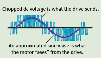
The problem is that even at low speed (low frequency), the square-wave’s amplitude is always at 650 Vdc bus voltage for 480-V motors. The resulting voltage rise time dv/dt from the insulated gate bipolar transistors (IGBTs) causes reflective-wave issues and electromagnetic interference (EMI) issues, something that wasn’t an issue with yesterday’s VFD inverters. Early generation inverters used silicon controlled rectifiers—SCRs—or bipolar junction transistors—BJTs—as the switching components to output power. These were much slower than modern VFDs using IGBTs at around 20 kHz. Though the higher frequency IGBTs makes for better control and more accurate response, the negative tradeoff is that it causes phenomena compromising the entire system … including the cables.
Reflected waves and corona inception voltage
One of the most pronounced problems is reflected waves. Remember that a motor’s stator windings are an inductor and inductors don’t pass current instantaneously. Instead, they must first build up a magnetic field. Because of the impedance mismatch between the cable and the motor, the extremely fast rise time of the dc pulses (dv/dt) causes voltage overshoots in the form of reflective waves at the cable to motor junction. Here a portion of the waveform’s leading edge reflects back through the cable when it hits the motor junction.
The incidence of voltage-wave reflections depends on two things:
• voltage rise time dv/dt
• the length of the motor cables, which behave as a transmission line.
The reflective waves can build, possibly surpassing the corona inception voltage (CIV) level.
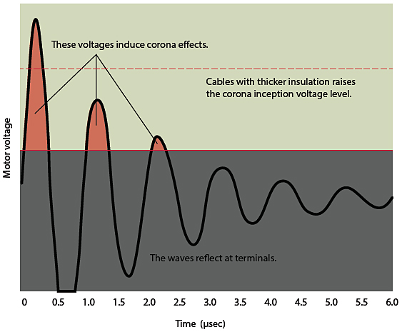
Corona is discharge from a localized electric field on an object that causes the ionization and electrical breakdown of adjacent air. It’s characterized by a colored glow (visible in the dark) and a hissing sound with intensity that increases with output voltage. A corona discharge can also generate ozone that destroys rubber. If sufficient moisture is present, this process can even generate nitric acid—a substance that slowly heats and melts common PVC electrical insulators in localized areas, which causes premature cable burnout.
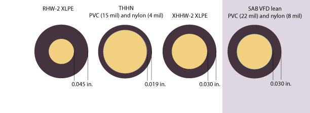
The solution here is to pick cables with PVC insulation that’s thicker than the listed National Electric Code (NEC) standards for THHN wire and even drive-manufacturer recommendations. Also note that per NEC Article 310.10, THHN PVC insulated cables should be used for dry and damp locations; for wet locations, designers should use cross-linked polyethylene (XLPE) XHHW or RHW-2, because heat generated by the creation of nitric acid forms a thermally isolating charred layer on the XLPE surface that can prevent further degradation.
For example, some Allen Bradley wire-selection flowcharts recommend that designers use PVC insulated cables with a minimum of 20-mil insulation for dry conditions and XLPE (XHHW-2) for wet conditions. The thicker insulation on cables reduces the harmful effects of reflective waves, as it increases the corona-inception voltage (CIV), the voltage level at which corona initiates.
For runs longer than 50 ft, PVC insulation should be a minimum of 20 mil—or use XLPE-insulated conductors.
VFD “IOC” faults
The higher frequency dc pulses also trigger false instantaneous-over-current (IOC) faults in smaller VFDs, particularly in drives 5 hp and less since the over-current set points are smaller. The high-frequency pulses can actually charge the capacitance between the conductors, drawing more current from the drive. Remember that cables can act as capacitors, with two conductors separated by a dielectric (the cable insulation). Therefore, it’s best to have cables with a lower dielectric constant to reduce this cable charging and minimize instantaneous over-current trips. To this end, pick PVC and XLPE cables that have thicker insulation so they’ll have lower dielectric values.
Common-mode currents
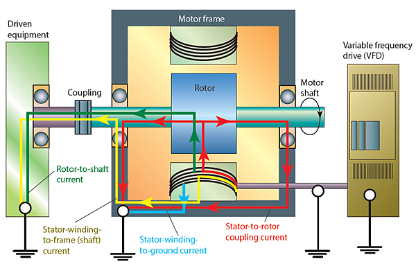
A typical three-phase sinusoidal power supply is balanced and symmetrical under normal conditions. This means that the vector sum of the three phases is always equal to zero. But that’s not true for VFDs that use dc pulses to create three-phase voltages. (The fundamental frequency of the output voltages is somewhat symmetrical, but it’s impossible to make the sum of the voltages zero.) The resulting neutral-point voltage—the center winding junction in a star-wound motor—is not zero. The unbalanced voltage here is the common-mode voltage source. So, whenever the sum of the three-phase voltage levels at this junction changes, a current proportional to that change must flow to earth. This current flows to earth through all the system components, sometimes forming detrimental ground loops.
Ground loops are unintended paths through an electrical interconnection system in which potentials (voltages) measured with respect to ground at either end of the path differ.
High levels of noise at anything from 60 Hz to 30 MHz can capacitively couple the motor windings to the motor frame and then ground. This noise can also capacitively couple from unshielded motor cables in conduit through ground straps or supports. These unintentional currents are troublesome for digital systems susceptible to the high-frequency noise generated by VFDs. In fact, even a small offset in potentials can make extraneous currents flow through grounds and change voltage-reference levels. To avoid this potentially damaging current, all grounding should tie to the same potential at the drive. In addition, avoid unshielded cables in metal conduit or trays—or else the conduit could conduct EMI and common-mode noise to the nearest earth ground and create ground loops.
High-frequency bearing and shaft currents
High-frequency common mode currents can also flow from the motor frame (the stator) through the bearings to the shaft on the driven machinery to ground through the capacitance between the bearings and the outer race. These bearing currents can cause electro-discharge machining (EDM) to occur. This EDM causes tiny pits in the bearing’s outer race, giving it a rough surface that can make the bearings fail. (For articles with images of bearing-race fluting caused by bearing currents, click here.)
In addition to the stator currents, there are also shaft currents (also called rotor currents) that flow in the motor. To mitigate these currents, there must be proper grounding with a good shield against noise and a low-impedance ground path back to the drive.
If there’s no conductive coupling between the rotor shaft and the driven equipment, engineers can incorporate shaft-grounding rings to direct the rotor currents back through the motor frame.
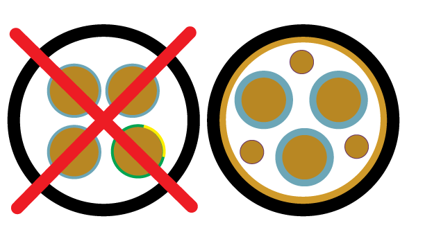
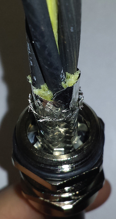
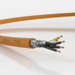
More specifically, for EMI and common-mode currents (which flow through low-impedance paths to ground—shaft bearings or metal-conduit connections, for example) designers should apply proper grounding techniques and good shielding practices to get these harmful signals to flow back to the drive through ground wires and cable shields with very low impedances. Standard cables provide enough grounding to protect people, but that’s not enough to protect equipment against high-frequency noise and common mode currents. That’s why for large motors, many motor manufacturers (including ABB) recommend cables that have a symmetrical arrangement of three phase leads and three earth conductors.
Electromagnetic interference
Electromagnetic interference (EMI) is disturbance that affects an electrical circuit due to either electromagnetic induction or electromagnetic radiation emitted from an external source. The effects from this interference can range from a simple degradation of data to a total loss of data. The source may be any object, artificial or natural, that carries rapidly changing electrical currents, such as an electrical circuit, the Sun or the Northern Lights.
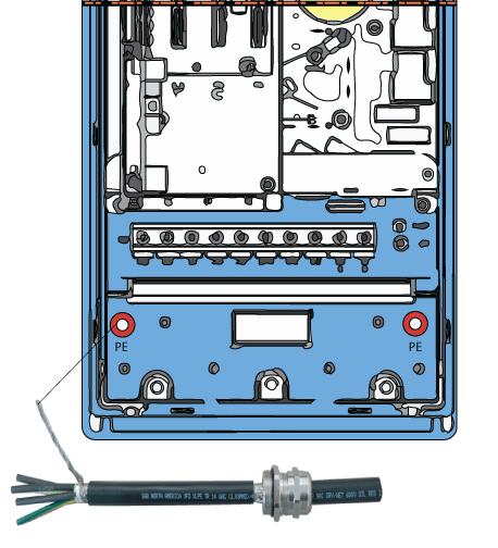
To prevent EMI in VFD systems, ABB recommends grounding the shield with 360° contact at the enclosure entrance and the motor, and to pigtail the shield to the PE terminal on the drive. Some cable manufacturers agree that this is the best solution … and offer a grounding connector with 360° contact for the entry of the cables to the enclosure.
Note that proper grounding of the enclosure and motor, followed by proper shielding of VFD cables, creates what is essentially a Faraday cage. A Faraday cage is an enclosure formed by conducting material. Such an enclosure blocks external static and non-static electric fields by channeling electricity through the enclosure to ground. This in turn makes for constant voltage on all sides of the enclosure. Because the difference in voltage is the measure of electrical potential, no current flows through the space.
To prevent electrical noise, always terminate shields at both ends—at the motor and the drive. The shield acts as a ground path for electrical noise and stray CMC, so proper termination is essential.
Due to the skin effect at high frequencies, don’t use a single terminated drain wire. It doesn’t provide adequate surface area to conduct the high frequency noise to ground. Rather, it’s best to tie the shield directly to the PE terminal at the drive. Because VFD signals have a very high frequency, they exhibit the skin effect on wires at those high frequencies.
As a review, the skin effect is a tendency for alternating current to flow mostly near the outer surface of an electrical conductor. The effect becomes more and more apparent as the frequency increases.
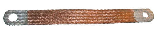
This is also why it’s best to use a ground strap instead of solid round wire for grounding.
Seven things to remember when installing cables on VFD systems
1. Some VFD cables have insulation that’s thicker than that required by code. They raise the corona inception voltage levels to extend cable life. Such cables also have lower capacitance values, which in turn makes for fewer instantaneous overcurrent faults on small drives.
2. PVC insulation is for dry and damp locations, and XLPE is for wet locations (per the National Electric Code or NEC). That’s because a corona discharge where there’s moisture makes nitric acid that can melt PVC, but actually chars and strengthens XLPE.
3. Drive manufacturer Allen Bradley offers a useful wire-selection flow chart; it can be used to identify suitable VFD cables. In general, cables with PVC insulation that’s 0.020 in. (20 mil) or thicker is okay in most applications, except for those in wet locations, or where there are longer cable runs.
4. Because VFDs have unbalanced three-phase vector sums, current is never equal to zero at neutral. That necessitates proper shielding and grounding paths with low impedance back to the drive (and to protect against the effects of common-mode currents and high-frequency bearing currents).
5. Never use unshielded cables in conduit or tray to prevent unintended paths to earth ground, creating ground loops. In addition, cables must have proper shielding and grounding where they connect to the drive enclosure and where they connect to the motor. For this, use EMC glands and shielded cables.
6. It is always best to tie the shield directly to the PE terminal at the drive (to avoid the skin effect from drain wires).
7. There’s no substitute for good VFD cables. Note that shaft-grounding rings only address shaft currents in certain cases and do not address stator currents. In a similar limitation, VFD output filters do not address common mode current and high-frequency bearing currents, so they are not a substitute for well-cabled machinery.
Article by Kevin Marston • Managing Director | SAB NORTH AMERICA


Leave a Reply
You must be logged in to post a comment.