
To understand a pull-up resistor, it helps to first understand how encoder output is generated. Incremental encoders can provide several types of digital output, with the three primary types being open collector, push-pull, and line driver. Open collector output is considered sinking, while the line driver type is considered sourcing, and push-pull output is both sinking and sourcing.
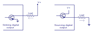
Image credit: circuits today.com
Line driver output is referred to as sourcing because it supplies current to the load. Line driver outputs are differential, meaning that they produce pairs of signals (A, A-; B, B-; etc.). The complementary signals are exact inverses of their main signals, so when the A signal is in the high state, the A- signal will be in the low state. This arrangement spreads any noise across both signals, which are evaluated at the receiver as differential, rather than absolute, levels. This gives the line driver output a high level of noise immunity.
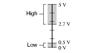
Image credit: Tony R. Kuphaldt, ibiblio.org
A push-pull output driver can either sink or source current to the load. The high level output is equal to the power supply, effectively “pushing,” or sourcing, current to the load from the power supply. The low level output equals the power supply common voltage (0 V) level, effectively “pulling,” or sinking, the load to ground.
The simplest type of output driver is the open collector, or NPN (sinking) output. An open collector driver sinks current from PNP (sourcing) inputs—either the PLC or motion controller. In the on state, it supplies a path to ground, and in the off state, it floats – that is, it is neither high nor low. So there must be a way to manipulate its voltage in order to indicate a logic high signal. This is where a pull-up resistor comes in.
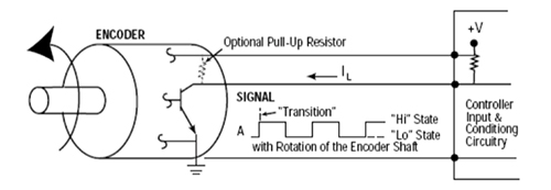
Image credit: Dynapar Corp.
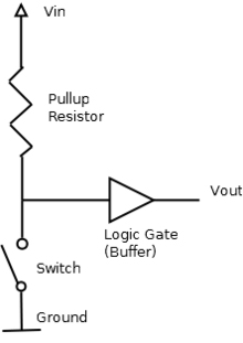 The basic function of a pull-up resistor is to ensure that when there is no input, a circuit takes on a default value. In other words, it sources current from the power supply to pull the voltage up to a specified value (typically the operating voltage) so that it can be read as a logic high signal. The output causes the voltage to drop to its low, or ground, state (0 V). This switching of the output pulses on and off creates a square wave.
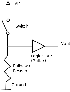
In contrast to pull-up resistors, pull-down resistors limit the current that can flow between the supply and ground and are sometimes used in encoder line driver and push-pull outputs.
Leave a Reply
You must be logged in to post a comment.