
Servomotors are electric motors that output motion under closed-loop control — so they rely on feedback from encoders or sensors … as well as a controller to process those signals for shaping the commands and corrections back to the motor. Usually these are rotary servomotors to output precise torque and speed — often for positioning.
So all servomotor systems include the aforementioned electric motor as well as feedback and electronic control of some form.
Servomotors work for machine axes that need to make complex moves or position loads with really high precision. Servomotors can also run at zero rpm while holding torque to keep a load at a set position, if that’s the goal.
Note that manufacturers classify motors for constant-speed tasks by horsepower — or torque at base speed. In contrast, servomotors operate over speed ranges so aren’t rated this way. Instead they have speed-torque curves that express continuous torque capabilities (that won’t threaten to overheat the motor) and intermittent or peak torque for acceleration.
So to pick a servomotor, define (using application inertia) how much load it will move. Then determine application speed or velocity — and how far and fast the load needs to travel. Calculating torque is next — and then plot them on the prospective motors’ torque-speed curves — as the servomotors’ continuous and peak torque limits over the axis’ full speed range. So is picking and sizing an appropriate servomotor complex? Often yes — but there are many manufacturer software programs out there to help make it easier. The other good news is that once a designer has the parameters for an axis and its motor, he or she can setup its drive to protect the rest of the system’s components by preventing excessive torques and other problematic conditions.
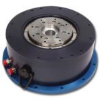
Many servomotors that aren’t direct drive have top speeds up to thousands of rpm — so to better leverage their full capabilities, designers will often combine such motors with gearing to trade an increase in output torque with lower output speed. Much of the time, this gearing takes the form of planetary or harmonic gearheads — precision arrangements with high accuracy and efficiency.
In a lot of cases, gearing even lets machine builders use smaller motors on axes — which equates to cost savings that may even offset the price of additional gearing.
Keep in mind that the term servomotor can mean different things depending on the context. Convention is that the term often (though definitely not always) refers to what industry calls dc motors — brushed and the costlier (but longer-lived) brushless servomotors.
Note that technically, dc brushless motors run off ac power — shaped into a square wave current that’s fed to the motor’s phases in a predefined sequence – so-called electronic commutation. What the industry calls an ac brushless motor is the same permanent-magnet synchronous design — just optimized to accept sinusoidal ac current into its phases instead. Some argue that we should forever rename dc brushless motors to trapezoidally wound motors — and (to be consistent) we should call ac brushless motors sinusoidally wound motors.
Just remember that brushed servomotors give linear and predictable performance that makes them easy to apply. Brushless motors usually run applications needing more torque; the only catch here is that their drives are more complex because commutation is done electronically and not mechanically as in brushed types. Industry also categorizes motors in part by their number of electrical phases. Brush DC servo motors as well as voice coil motors are in fact single-phase motors, whereas brushless servo motors most commonly have three phases.
Some sources classify induction-motor-based designs running off vector controls as servomotor setups where the design incorporates feedback (usually from an encoder) to track and control speed and sometimes even position. These induction motors typically adhere to NEMA or metric standards, whereas other servomotor offerings are less uniform, as their design roots are in application-specific setups.
Leave a Reply
You must be logged in to post a comment.