by Dan Montone, PITTMAN Motors/AMETEK Precision Motion Control, Harleysville, PA
Motor performance changes with temperature. Understanding the effects of heat and temperature changes will help in selecting the right motor for an application.
When applying DC motors to any type of application, temperature effects need to be considered in order to properly apply the motor. Performance will change as the motor temperature increases. When reviewing DC motor curves, the user needs to ask the question “Do these curves represent performance of the motor at room temperature, or do these curves illustrate performance at the maximum rated temperature?” Depending on the temperature and the required operating point on the motor curve, the performance difference between “cold” and “hot” conditions can be significant.
Once a motor design is finalized including motor dimensions, magnetic circuit, and motor winding configuration, several characteristics that determine motor performance become “theoretically” fixed; the torque constant (KT), voltage constant (KE), and motor terminal resistance (Rmt). These three values will determine the output torque, motor speed, and the resulting output power at any point on the motor curve at a given terminal voltage, as well as the overall slope of the motor curve.
Table 1 — Symbols and Units
|
SYMBOL |
DESCRIPTION |
UNITS |
|
α |
temperature coefficient |
/°C |
|
I |
Current |
A |
|
I0 |
No load current |
A |
|
ILR |
Locked rotor current |
A |
|
KE |
Voltage constant |
V/(rad/s) |
|
KT |
Torque constant |
Nm/A |
|
K(i) |
KT or KE (initial “cold”) |
Nm/A or V/(rad/s) |
|
K(f) |
KT or KE (final “hot”) |
Nm/A or V/(rad/s) |
|
n |
Speed |
RPM |
|
n0 |
No load speed |
RPM |
|
P |
Power |
W |
|
Pout |
Output power |
W |
|
Pmax |
Max power |
W |
|
Pmax(i) |
Max power (initial “cold”) |
W |
|
Pmax(f) |
Max power (final “hot”) |
W |
|
Ploss |
Dissipated power |
W |
|
T |
Motor torque |
Nm |
|
TLR |
Locked rotor torque |
Nm |
|
Rm |
Motor regulation |
RPM/Nm |
|
Rmt |
Motor terminal resistance |
Ω |
|
Rmt(i) |
Motor terminal resistance (initial “cold”) |
Ω |
|
Rmt(f) |
Motor terminal resistance (final “hot”) |
Ω |
|
Ѳi |
Motor temperature (initial “cold”) |
°C |
|
Ѳf |
Motor temperature (final “hot”) |
°C |
|
Ѳr |
Motor temperature rise |
°C |
|
VT |
Motor terminal voltage |
V |
|
ω |
Angular velocity |
rad/s |
|
ω0 |
No load angular velocity |
rad/s |
Motor Constants Aren’t Really Constant
The torque constant and voltage constant are determined during the design phase and are a function of the overall magnetic circuit design. They are always equal when using SI units. For example, if the motor KT = 0.1 Nm/A, then motor KE = 0.1 V/(rad/s) assuming Nm and V/(rad/s) are the units used. Motor terminal resistance is also determined in the design phase by the number of coils, number of coil turns, and magnet wire diameter. These principles apply to both brush and brushless DC motors.
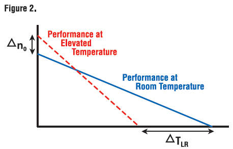
The phrase “motor constants,” however, is somewhat of a misnomer. Winding resistance and permanent magnet flux density will change as temperature changes. As the motor temperature increases, winding resistance will increase based on the temperature coefficient of copper. The flux density of the permanent magnets will also decrease as a function of temperature. Changes in these two key components of the motor will result in an increase in motor no-load speed and a decrease in motor locked rotor torque altering the overall slope of the motor curve. Once the user understands this concept, it becomes clear that motor performance determined using a rapid dynamometer test with a room temperature motor is significantly different than the motor performance when operated at its maximum temperature under load.
The DC Motor Curve
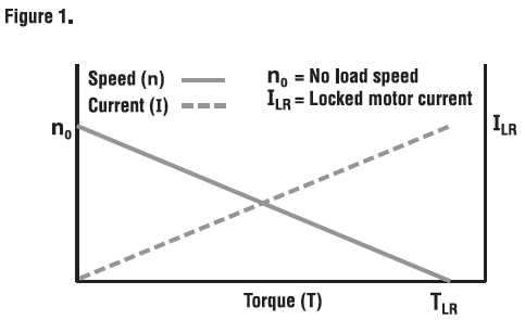
DC motor performance curves can be generated under various conditions. For example, the motor curve illustrated in Figure 1 was created using a rapid test on a motor dynamometer. The test was done by quickly loading the motor from no-load to locked rotor (stall) using a fixed terminal voltage from a power supply with low output impedance. A test like this is done to get a “baseline” measure of motor performance while the motor is at room temperature. Motor shaft speed and current are plotted as a function of motor torque. From this test and a few resistance readings, the torque constant, voltage constant, and terminal resistance values can be determined. This information is very useful to ballpark basic motor performance and can be sufficient for an application that requires intermittent operation with a long rest period between each duty cycle.

In applications such as repeated point-to-point moves, applications requiring frequent starting and stopping of a high inertia load, or applications that require the motor to be moving for long periods of time (such as a fan application) the motor data illustrating performance at room temperature is not adequate and can result in misapplication of the motor or exceed the motor’s maximum temperature rating.
As the motor temperature increases, the resistance will increase and the torque constant and voltage constant will decrease. This results in an increase in no-load speed and a decrease in locked-rotor torque. Figure 2 illustrates an example of both “cold” and “hot” running conditions of the same DC motor. The “hot” motor curve demonstrates how much the performance can change when operating the motor at an elevated temperature.

Temperature Effects of Motor Winding Resistance
Motor winding resistance (Rmt) is the main cause of heat generation within the motor. In order for any electric motor to generate torque, current needs to be forced through the motor windings. Copper is an excellent conductor, however, it’s not perfect; material physics and impurities will cause the atoms to vibrate at a faster rate as more current flows. The result is a steady temperature increase in the motor windings. All metal conductors have a positive temperature coefficient of resistance. This means as temperature increases, the resistance of the material also increases as a function of the type of conductor used. Electric motors typically use copper conductor material, except in special cases. Many induction motor squirrel cages use cast aluminum for ease of manufacturing, but the vast majority of motors use copper magnet wire. Table 2 lists examples of common metals used in electrical and electronic devices and their respective temperature coefficients (α).
Table 2 — Temperature Coefficients for Various Conductor Materials
|
Conductor Material |
αconductor (/°C) |
|
Silver |
0.0038 |
|
Gold |
0.0037 |
|
Copper |
0.0040 |
|
Aluminum |
0.0043 |
Equations 1 and 2 illustrate the relationship between winding temperature, winding resistance, and watts dissipated.
Equation 1 – Change in Winding Resistance
Rmt(f) = Rmt(i) x [1 + α (ϴf – ϴi)]
Equation 2 – Watts Lost Due To Winding Resistance
Ploss = I2 x Rmt
Temperature Effects On Magnetic Flux Density
The motor torque constant (KT) and voltage constant (KE) are directly related to the magnetic flux density (Br) of the permanent magnets. Depending on the physics of the magnet material used, overall flux density will change at a given percentage with an increase in magnet temperature. As the material temperature increases, atomic vibrations cause once-aligned magnetic moments to “randomize” resulting in a decrease in magnetic flux density. Assuming the motor is operating within its intended design window, the decrease in flux density is temporary and will begin to recover as the magnet cools. If the maximum temperature rating of the magnets is exceeded, however, partial demagnetization will occur and permanently alter the performance of the motor.
Table 3 — Temperature Coefficients for Various Permanent Magnet Materials
|
Magnetic Material |
αmagnet (/ °C) |
Tmax (°C) |
|
Ceramic |
-0.0020 / °C |
300 °C |
|
Samarium Cobalt (SmCo) |
-0.0004 / °C |
300 °C |
|
Aluminum Nickel Cobalt (AlNiCo) |
-0.0002 / °C |
540 °C |
|
Neodymium Iron Boron (NdFeB) |
-0.0012 / °C |
150 °C |
The values in Table 3 represent average figures for material classes. Specific magnet grades within a class of materials will vary from the values given below. For example, some grades of Neodymium magnets can exceed the listed operating temperature of 150°C. The table illustrates relative differences between temperature characteristics of various materials. If exact values are needed, it’s recommended to consult an application engineer at the motor manufacturer for specific information.
Equation 3 – Change in KT and KE (KT=KE when using SI units)
K(f) = K(i) x [1 + αmagnet (ϴf – ϴi)]
A question often asked by users is the relationship between KT and KE under elevated temperature. In the case of using SI units, one will always equal the other; however, both will change equally with temperature. In the case of using English units, KT and KE are expressed in oz-in./A (lb-in./A, lb-ft/A, etc.) and V/krpm. One does not equal the other when using these units, but both quantities will decrease in the same proportion with elevated temperature.
How does this affect overall motor performance?
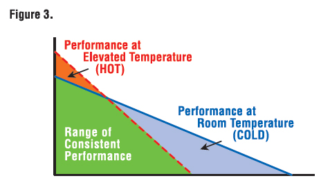
At an elevated motor temperature, the slope of the DC motor curve increases as a result of an increase in no-load speed and a decrease in locked rotor torque (sometimes referred to as stall torque). Figure 3 illustrates the total area beneath a particular motor curve that can be considered the range of consistent performance between room temperature and maximum rated motor temperature.

Another term referring to the slope of the DC motor curve is “regulation.” Motor regulation describes how much the shaft speed will change with a given change in shaft load when applying a fixed terminal voltage to the motor (operating as an open loop system). A flatter speed-torque curve will result in a smaller change in shaft speed with increased load. As the motor temperature increases and the curve becomes steeper, shaft speed will drop more for the same increase in load.
Equation 4a – Theoretical Motor Regulation Using Constants
Rm = 9.5493 x [Rmt / (KT x KE)]
Equation 4b – Motor Regulation Using A Performance Curve
Rm = n0 / TLR
Equations 4 and 5 can be used to illustrate the dramatic effect on motor performance resulting from a decrease in magnetic flux and increase in winding resistance. Although there will be an increase in motor no-load speed as well as a decrease in locked rotor torque, the difference in “cold” versus “hot” locked rotor torque is greater compared with the difference in “cold” versus “hot” no-load speed.
The locked rotor torque is heavily dependent on both the resistance (Rmt) and torque constant (KT). Although the no load speed will also be affected by the higher resistance at an elevated temperature, the resistance factor has a much smaller effect on no-load speed because it’s multiplied by the no load current (I0), a relatively small number (compare equation 5b and 5c).
Equation 5a – Motor Locked Rotor (Stall) Current
ILR = VT / Rmt
Equation 5b – Motor Locked Rotor (Stall) Torque
TLR = ILR x KT = (VT / Rmt) x KT
Equation 5c – Motor No Load Speed
n0 = 9.5493 x [(VT – I0 x Rmt) / KE]
The user needs to be careful when designing the system to insure the shaft speed meets the minimum specification at a given load at an elevated motor temperature. In a more complex motion system using a closed-loop controller, shaft speed can be controlled within a given range to remain “fixed” as the load requirements change. The example that follows assumes the motor is operated open-loop with a regulated DC terminal voltage.
This feature is Part I of a two part series. Part II will appear in the December issue.
AMETEK Precision Motion Control
www.ametek.com


Leave a Reply
You must be logged in to post a comment.