
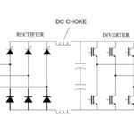
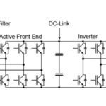
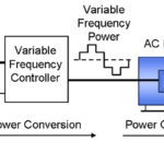
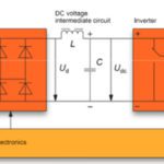
A variable frequency drive alters the speed of an AC induction motor by rectifying incoming AC power to DC, storing the DC power in a bus, and then converting the DC power back to AC at the voltage and frequency required to meet the load demands. Although this matching of the motor speed to the load provides significant energy savings, it also creates distortions in the voltage and current waveforms. Two devices that can protect drives, motors, and other equipment from damage caused by these current and voltage distortions are line reactors and drive isolation transformers.
Both line reactors and drive isolation transformers mitigate or resolve certain power problems that occur due to VFD operation, primarily by adding impedance to the supply line.
Variable frequency drives (VFDs) are considered non-linear loads because they draw current from the power supply only when required, creating non-linear current waveforms that contain harmonic distortions. When harmonic distortions in current contain very high peaks, they can also cause the voltage waveform to be distorted.
Line reactors and drive isolation transformers (DITs) add impedance to the supply line, before the VFD. This added impedance slows the rate of change of the current and lowers the peak current level, reducing harmonic distortion in the current waveform. By controlling the current component of power, this added impedance also reduces harmonic distortion of the voltage waveform.
For drives that use diode rectifiers (the simplest design), impedance added ahead of the drive can prevent tripping and failures due to voltage surges and high-frequency disturbances. And for VFDs that use SCRs (silicon controlled rectifiers), added impedance reduces voltage notching caused by the switching of the SCRs.
A line reactor is a type of inductor, made from a coil of wire — typically wrapped around an iron core — that stores energy in a magnetic field as current flows through it. Inductors, including line reactors, add impedance, meaning they oppose any change in the current flowing them.
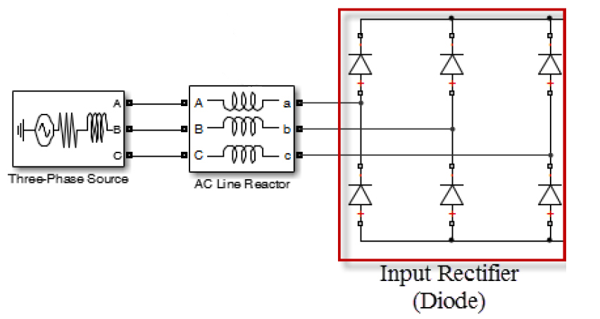
Image credit: Kevin Hinds, NAVSEA
Drive isolation transformers also add impedance to the supply line and provide many of the same benefits as line reactors. The primary difference is that line reactors have a single winding per phase, whereas drive isolation transformers have two windings — a primary and a secondary — that are separated by an air gap. This air gap electrically isolates the VFD input from the power source.
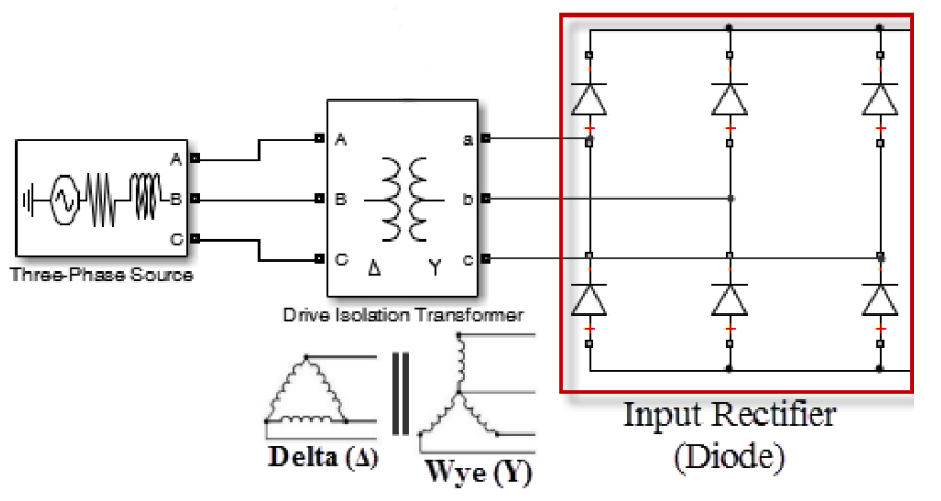
Image credit: Kevin Hinds, NAVSEA
If the secondary winding of a drive isolation transformer is wye connected, it can be grounded to prevent the transfer of common-mode noise and high transient voltages, both from the power source to the drive and from the drive to the power source. If the primary and secondary windings are covered with an electrostatic shield, the DIT will also protect the drive against common-mode voltage disturbances.
Any transformer that consists of a primary and secondary winding that are not electrically connected is an isolation transformer.
Drive isolation transformers tend to be larger and more expensive than line reactors, but are typically recommended when isolation is required between the power supply and the drive, or when the incoming AC voltage needs to be stepped up or stepped down for the VFD.
Leave a Reply
You must be logged in to post a comment.