• Skip to primary navigation
  • Skip to main content
  • Skip to primary sidebar
  • Skip to footer
  • Advertise
  • Subscribe

Motion Control Tips

Automation • Motion Control • Power Transmission

  • News
    • Industry News
    • Editor Blogs
  • Controls
    • HMIs
    • PC-Based Controllers
    • PLCs + PACs
    • Stand-Alone Controllers
    • Software
  • Drives
    • Servo Drives
    • Stepper Drives
  • Encoders
    • Absolute Encoders
    • Incremental Encoders
    • Rotary Encoders
  • Mechanical
    • Bearings
    • Brakes + Clutches
    • Belt + chain
    • Couplings
    • Gears + Gearing
    • Lubrication
    • Shock + Vibration Mitigation
    • Springs + Rings + Seals
  • Linear
    • Actuators
    • Linear Motors
    • Linear Encoders
  • Motors
    • AC Motors
    • DC Motors
    • Brushless Motors
    • Gearmotors
    • Piezo Motors
    • Servo Motors
    • Stepper Motors
  • Systems
    • Conveyors + linear transport systems
    • Gantries + Stages
    • Rotary Tables
    • Grippers + End Effectors
    • Robotics
  • Networks
    • Connections + Sliprings
    • Fieldbuses
    • I/O
    • Sensors + Vision
  • Resources
    • FAQs
      • Motion Casebook
      • Motion Selection Guides
    • Suppliers
    • Video
You are here: Home / Encoders / What are geared cam limit switches?

What are geared cam limit switches?

October 28, 2020 By Danielle Collins Leave a Comment

geared cam limit switches
Image credit: Ametek

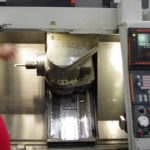
Electromechanical switches are often placed at the ends of linear axes to indicate the limits of travel. But for applications with rotary — rather than linear — motion, geared cam limit switches can perform a similar function by tracking rotations of the motor shaft and triggering switches to stop movement when the specified number of rotations has been reached.

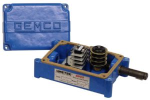
To measure shaft rotations, geared cam limit switches — also referred to as rotary limit switches — use a geared input and a series of cams. The input shaft of the rotary switch assembly is coupled to the motor, and as the motor shaft rotates, it turns the input gear. Cams are mounted concentrically with the gears, so as the gears turn, the cams rotate, and rocker arms attached to the cam lobes trip switches at set positions.
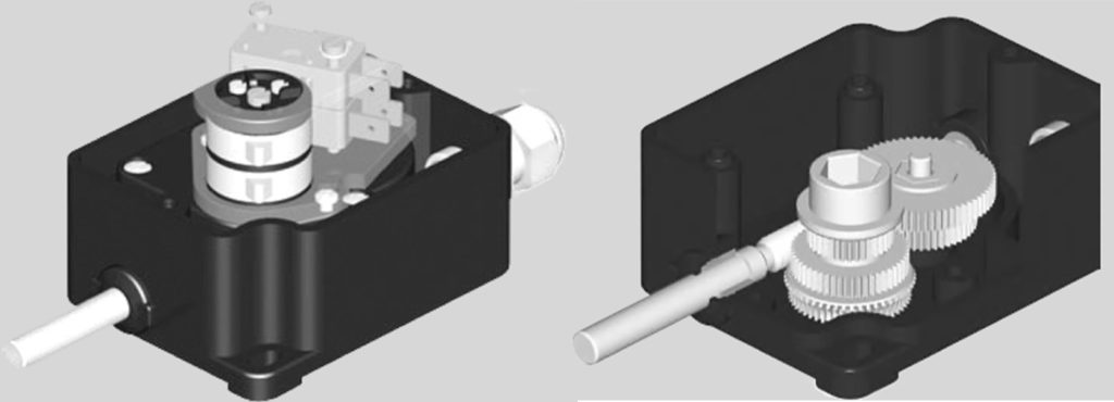
geared cam limit switches
Switches are activated by cams (left) that are driven by a geared input shaft (right).
Image credit: TER

The input gear is typically a worm gear, but planetary and spur gear versions are also available, with the gear type depending primarily on the required gear ratio. The positions (rotations) at which the switches are activated depend on the ratio of the input gear and the design of the cam lobes. Geared cam limit switches are suitable for a wide range of applications, speeds, and switching requirements, with manufacturers offering gear ratios ranging from 1:1 up to 9000:1 or higher on some designs.

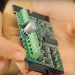
Each limit switch assembly uses at least two cams and two switches (one for each end, or upper and lower limit, of travel), although many designs incorporate four or more switches for intermediate position control as well. The cams can be manually adjusted via fine-pitch screws to precisely “dial-in” the switching positions. More sophisticated geared cam limit switches allow a potentiometer, resolver, or encoder to be integrated with the switch assembly, so the device provides not only the safety of the limit and position switches, but also position feedback and control.

geared cam limit switches
For position feedback and control, some designs integrate a potentiometer, resolver, or encoder.
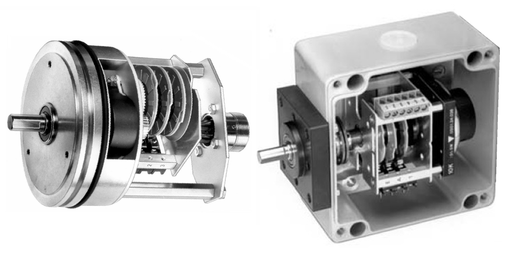
Image credit: Micronor

The integrated switches are typically normally closed (NC) types with positive-opening contacts, making them suitable for safety applications. The use of positive-opening, snap-action contacts also means there is no minimum motor speed required in order for the switches to operate properly, and maximum allowable speeds typically range from 500 to 2000 rpm.

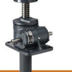
Geared cam limit switches can be used for any application where switches should be activated based on rotations (partial or multiple) of a motor shaft, including industrial equipment such as packaging machines and winders. And they’re often used for lifting and lowering equipment such as hoists and cranes, where linear movement of the device is difficult to measure directly.

You Might Also Like

Filed Under: Encoders, FAQs + basics, Featured, Sensors + Vision

Reader Interactions

Leave a Reply

You must be logged in to post a comment.

Primary Sidebar

LEARNING CENTER

Design World Learning Center

Motion Control Handbook

“mct
EXPAND YOUR KNOWLEDGE AND STAY CONNECTED
Get the latest info on technologies, tools and strategies for Design Engineering Professionals.

RSS Featured White Papers

  • Robotic Automation is Indispensable for the Logistics Industry’s Continued Growth and Success
  • Reliable Linear Motion For Packaging Machines
  • Polymers Outperform Metals In Precision Gearing

Footer

Motion Control Tips

DESIGN WORLD NETWORK

Design World Online
The Robot Report
Coupling Tips
Linear Motion Tips
Bearing Tips
Fastener Engineering.
Wire and Cable Tips

MOTION CONTROL TIPS

Subscribe to our newsletter
Advertise with us
Contact us
About us

Copyright © 2025 · WTWH Media LLC and its licensors. All rights reserved.
The material on this site may not be reproduced, distributed, transmitted, cached or otherwise used, except with the prior written permission of WTWH Media.

Privacy Policy | RSS