
In any system where a motor drives a load to achieve precise positioning, velocity, or torque, the ratio of the load inertia to the motor inertia plays a significant role in determining the motor’s ability to effectively and efficiently control the load, especially during acceleration and deceleration portions of the motion profile.
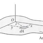
In this context, the inertia we’re referring to is mass moment of inertia (sometimes referred to as rotational inertia), which is an object’s resistance to change in rotational speed. An object’s mass moment of inertia is determined by its mass and geometry — specifically, the radius between the object’s center of mass and the point around which the object rotates.
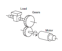
Image credit: Omron Industrial Automation
If the inertia of the load is significantly higher than the inertia of the motor, the load will essentially try to “drive” the motor, and the motor will have a difficult time achieving the desired position (or speed or torque). In an attempt to control the load, the motor will draw higher current, which decreases efficiency and increases wear on the motor and electrical components.
On the other hand, if the inertia of the motor is significantly higher than inertia of the load, it’s likely that the motor is oversized, which has negative implications throughout the system — including higher initial cost, higher operating cost, larger footprint, and the need to oversize other components, such as mounting hardware, couplings, and cables.
If the inertia ratio is too high — that is, if the load inertia is much higher than the motor inertia, causing problems with positioning accuracy, settling time, or control of velocity or torque — the load inertia that is seen by, or reflected to, the motor can be decreased by adding a gear set or gearbox between the motor and the load.
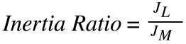
JL = inertia of load reflected to motor
JM = inertia of motor
Adding a gear set or a gearbox to a motor-driven system reduces the load inertia by the inverse square of the gear ratio, meaning that even a relatively low gear ratio can have a significant effect on the inertia ratio.
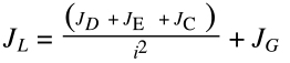
JL = inertia of load reflected to motor
JD = inertia of drive (ball screw, belt, rack & pinion)
JE = inertia of external (moved) load
JC = inertia of coupling
JG = inertia of gear set or gearbox
i = gear ratio
Note that the inertia of the gear set or gearbox (JG) is added to the load inertia, but its effect is typically small compared to the reduction provided by the gear ratio.
In addition to optimizing the load-motor inertia ratio, gearboxes are often used in motion control applications to increase the torque delivered to the load from the motor, but they also decrease the rotational speed delivered to the driven component from the motor, by an amount equal to the gear ratio. This is why gearboxes are often referred to as “gear reducers” or “speed reducers.”
In other words, if a motor running at 1200 rpm is driving a load through a 3:1 gearbox, the rotational speed delivered to the load will be 400 rpm (1200 ÷ 3). This reduction in speed can enable the system to operate at a more favorable location on the motor’s speed-torque curve.
Although it is possible to use a gearbox or gear set that is configured to reduce torque (and increase speed), in motion control applications, a more typical solution would be to choose a smaller motor.
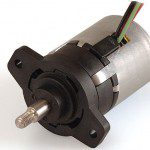
Feature image credit: M. M. Nazari

Leave a Reply
You must be logged in to post a comment.