• Skip to primary navigation
  • Skip to main content
  • Skip to primary sidebar
  • Skip to footer

Motion Control Tips

Automation • Motion Control • Power Transmission

  • News
    • Industry News
    • Editor Blogs
    • Video
  • Controls
    • HMIs
    • PC-Based Controllers
    • PLCs + PACs
    • Stand-Alone Controllers
    • Software
  • Drives
    • Servo Drives
    • Stepper Drives
  • Encoders
    • Absolute Encoders
    • Incremental Encoders
    • Rotary Encoders
  • Mechanical
    • Bearings
    • Brakes + Clutches
    • Belt + chain
    • Couplings
    • Gears + Gearing
    • Lubrication
    • Shock + Vibration Mitigation
    • Springs + Rings + Seals
  • Linear
    • Actuators
    • Linear Motors
    • Linear Encoders
  • Motors
    • AC Motors
    • DC Motors
    • Brushless Motors
    • Gearmotors
    • Piezo Motors
    • Servo Motors
    • Stepper Motors
  • Systems
    • Conveyors + linear transport systems
    • Gantries + Stages
    • Rotary Tables
    • Grippers + End Effectors
    • Robotics
  • Networks
    • Connections + Sliprings
    • Fieldbuses
    • I/O
    • Sensors + Vision
  • FAQs
    • Motion Casebook
    • Motion Selection Guides
  • Suppliers
You are here: Home / FAQs + basics / Worm gears: What are they and where are they used?

Worm gears: What are they and where are they used?

October 26, 2017 By Danielle Collins Leave a Comment

Worm gears are found in industrial applications, heavy equipment, and even consumer applications. Although their efficiency is relatively low, they can provide very high reduction ratios and, in many cases, are self-locking.


worm gears
Image credit: Nord Drivesystems

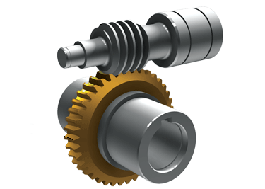
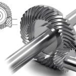
Worm gears are constructed of a worm and a gear (sometimes referred to as a worm wheel), with non-parallel, non-intersecting shafts oriented 90 degrees to each other. The worm is analogous to a screw with a V-type thread, and the gear is analogous to a spur gear. The worm is typically the driving component, with the worm’s thread advancing the teeth of the gear.

Like a ball screw, the worm in a worm gear may have a single start or multiple starts – meaning that there are multiple threads, or helicies, on the worm. For a single-start worm, each full turn (360 degrees) of the worm advances the gear by one tooth. So a gear with 24 teeth will provide a gear reduction of 24:1. For a multi-start worm, the gear reduction equals the number of teeth on the gear, divided by the number of starts on the worm. (This is different from most other types of gears, where the gear reduction is a function of the diameters of the two components.)

worm gears
The worm in a worm gear assembly can have one start (thread) or multiple starts.
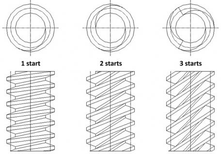
Image credit: Kohara Gear Industry Company, Ltd.

The meshing of the worm and the gear is a mixture of sliding and rolling actions, but sliding contact dominates at high reduction ratios. This sliding action causes friction and heat, which limits the efficiency of worm gears to 30 to 50 percent. In order to minimize friction (and therefore, heat), the worm and gear are made of dissimilar metals – for example, the worm may be made of hardened steel and the gear made of bronze or aluminum.

Although the sliding contact reduces efficiency, it provides very quiet operation. (The use of dissimilar metals for the worm and gear also contributes to quiet operation.) This makes worm gears suitable for use where noise should be minimized, such as in elevators. In addition, the use of a softer material for the gear means that it can absorb shock loads, like those experienced in heavy equipment or crushing machines.

The primary benefit of worm gears is their ability to provide high reduction ratios and correspondingly high torque multiplication. They can also be used as speed reducers in low- to medium-speed applications. And, because their reduction ratio is based on the number of gear teeth alone, they are more compact than other types of gears. Like fine-pitch lead screws, worm gears are typically self-locking, which makes them ideal for hoisting and lifting applications.

You may also like:

  • rack and pinion
    Rack and Pinion Drive System: What Is It?
  • hypoid gearboxes
    Hypoid gearboxes: What are they and where are they used?

  • Gearboxes and gear motors market growing, says F&S Mechanical Power…
  • gearbox
    What is a gearbox?
  • gearing
    How to get zero backlash out of gearing?

Filed Under: FAQs + basics, Featured, Gears + Gearing

Reader Interactions

Leave a Reply Cancel reply

You must be logged in to post a comment.

Primary Sidebar

MOTION DESIGN GUIDES

“motion

“motion

“motion

“motion

“motion

POWER TRANSMISSION REFERENCE GUIDE

RSS Linear Motion Tips

  • Haydon Kerk Pittman launches compact Z-Theta motion platform
  • Three easy ways to specify application requirements for linear motion systems
  • Sourcing linear motion solutions from NSK’s global manufacturing sites
  • Ride the wave of electrification: Off-highway designs with linear actuators
  • What are capacitive sensors and where are they used?
Subscribe Today

RSS Featured White Papers

  • Identifying Best-Value Linear Motion Technologies
  • Learn how to reduce noise and distortion in encoders’ signals
  • Helical Planetary Gearboxes: Understanding The Tradeoffs
Tweets from https://twitter.com/Motion_Control/lists/motion-control-tweets

Footer

Motion Control Tips

DESIGN WORLD NETWORK

Design World Online
The Robot Report
Coupling Tips
Linear Motion Tips
Bearing Tips
Fastener Engineering

MOTION CONTROL TIPS

Subscribe to our newsletter
Advertise with us
Contact us
About us
Follow us on TwitterAdd us on FacebookAdd us on LinkedInAdd us on YouTubeAdd us on Instagram

Copyright © 2021 · WTWH Media LLC and its licensors. All rights reserved.
The material on this site may not be reproduced, distributed, transmitted, cached or otherwise used, except with the prior written permission of WTWH Media.

Privacy Policy | RSS