Updated July 2016 by Lisa Eitel || Servo systems provide amazing levels of speed, accuracy, and flexibility in automated equipment when the correct servo is chosen for the application. Unfortunately, choosing the wrong servo can lead to difficulty in tuning, poor accuracy, or underwhelming performance.
With so many different servos to choose from, how do you ensure that the right one was chosen? Fortunately, the process of choosing the right servo motor and drive, known as sizing, can be broken down into eight simple steps.
1. Determine required voltage.
The first and easiest factor to consider is the available power for the equipment. Servos are available in 100 VAC, 200 VAC, and 400 VAC models, and are compatible with single phase or three-phase power.
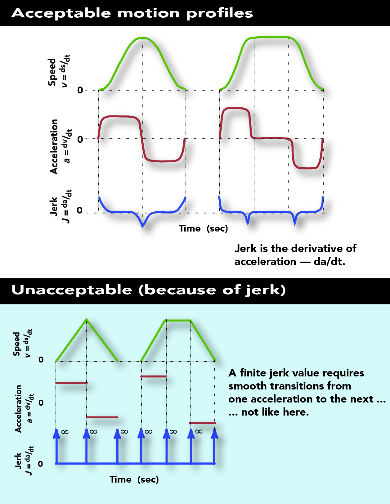
2. Define what the application’s motion profile looks like.
For equipment that performs a repetitive operation, plot out the required motor speeds throughout the cycle. Be sure to allow for acceleration and deceleration time; servomotors are not magic, and cannot make step changes in speed. For non-repetitive operations such as milling, calculate the peak speed and acceleration required for the application.
3. Determine how much torque the motion application needs.
Torque is how much “muscle” it takes to rotate a mechanism, and comes from three different sources: accelerating the mechanism’s inertia, friction, and external forces such as pressing against an object or gravity. This is the most difficult part to calculate accurately, but is also the most forgiving part of the selection process. Calculate the inertia of each component of the system and add the values. The formulas for calculating rotational inertia of various shapes are readily available on the Internet.
Multiply the acceleration by the load inertia to calculate the load’s acceleration torque. Calculate friction forces for sliding loads, gravitational forces for vertical loads, and any external forces. Multiply each force by the radius it is acting on (known as the “moment”) to calculate the torque.
Calculate the peak torque by adding up all the torque values in the worst-case scenario. This is typically when the fastest acceleration is occurring or when there is the most mass on the machine. Add up the torque values from external forces, gravity and friction to calculate the continuous torque requirement. Ideally, the continuous torque requirement would use a root-mean-squared (RMS) calculation, but this is tedious without the help of a software tool.
4. Calculate the motion system’s optimal inertia ratio.
Calculating inertia ratio is often overlooked by newcomers to servo sizing, but is arguably the most important factor in determining the performance of a servo system. Inertia ratio is the ratio of the load’s inertia divided by the motor’s rotor inertia divided by the square of the gear reduction.
To use a boxing analogy, if torque is how strong the fighter is, inertia ratio is the weight class. Not only does the servo system need to have enough torque to move the load, it must have the ability to accurately control the load. In an ideal world, the mechanism would be mechanically rigid and torque from the motor would be transferred smoothly and without delay to the load. In the real world, couplings flex, belts and chains stretch, and gears have backlash.
These imperfections can be minimized but not completely eliminated. When the motor begins to move, the machine winds up like a spring, and begins to push back on the motor with some tiny delay. This spring effect is magnified with large inertia ratios.
Servo systems use the feedback from the built-in encoder and the PID algorithm in the amplifier to accurately position the motor, but this tiny spring delay can cause oscillations and loss of control if the loop gains are too high. Reducing the gain will stop the oscillation, but at the cost of responsiveness.
While basic servo drives may require inertia ratios of 3:1 or smaller, high performance servo drives have auto-tuning, vibration suppression, resonance filters, and disturbance compensation functions that allow up to a 30:1 inertia ratio without sacrificing performance. A ratio of 1:1 will give excellent performance, but usually results in an oversized motor. Ratios less than 1:1 waste power with no performance advantage.
5. Choose a servo motor — tentatively.
At this point, the key criteria for choosing a servo motor have been defined and it is time to browse the product selection guide to find the motor that matches these requirements.
Find a motor and drive that matches the supply voltage, has a rated speed, continuous torque, and peak torque rating that exceeds the values calculated above. Look at the motor’s rotor inertia to find one that satisfies the inertia ratio requirement for the servo drive you are using.
Frequently, there may be several motors with similar torque and speed characteristics but different rotor inertias. If there is a motor that is a close match, you are finished. If not, gearing can be applied to match the motor and load more closely.
6. Determine what kind of servo gearing will work.
Servomotors can produce their full rated torque from zero rpm up to many thousands of rpm. Few machines can take advantage of these speeds without gear reduction. Gear reduction matches the servo to the load in three ways; reducing the speed, increasing the torque, and lowering the inertia ratio. Speed is reduced proportional to the gear ratio, torque is increased proportional to the gear ratio, and most importantly, the inertia ratio is lowered by the square of the gear ratio. Gearbox manufacturers list the inertia of the servo-grade gearboxes, making it easy to include the gearbox inertia into the torque and inertia calculations.
7. Choose a motor — for real this time.
In Step 5 — tentative motor selection — most of the motors available likely were capable of far higher speeds than needed. Divide the motor speed by the required speed and round down to get a starting gear ratio. Then divide the required torque by the gear ratio to find the new required torque. This will narrow the choices down to just a couple of motors.
Next, find a motor with an acceptable inertia ratio. If two motors look equal, choose the one with the lower inertia ratio. Repeat this step a couple of times using motors with different rated speeds, as it’s possible that more than one good solution exists.
8. Round out the design with a servo drive and other power-transmission components.
Once the servomotor has been selected, choose a servo drive rated for the correct input voltage and with sufficient output current to drive the servo motor.
Servo drives can be controlled via several different interface types. These interfaces include pulse-and-direction digital control, analog control, and other servo networks. A servo network provides high-speed control and feedback, reduced wiring, and superior diagnostics capabilities compared to the other interfaces.
Finally, choose any options such as keyed motor shafts, shaft seals, holding brakes for vertical loads, or external braking resistors.
Selecting the best servo system for an application is a skill that improves with practice. When in doubt, it’s a good idea to verify your results with the manufacturer or distributor.




Leave a Reply
You must be logged in to post a comment.