by Mike Peterson, Roboteq, Inc., Scottsdale, AZ
A progressive regenerative braking technique uses real-time speed sensing.
One of the most interesting features of electric motors when used in drive train applications is that they can also behave as generators, recharging a vehicle’s battery while braking. Some motor controllers can be programmed to take advantage of this characteristic to create regenerative braking in a controlled and progressive manner.

Basic Electrical Theory
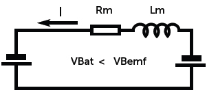
The simplified model of a motor is a resistor in series with an inductor and a voltage generator. The resistor and inductor are simply the resistance and inductance of the electromagnets inside the motor. The voltage generator represents the voltage created by the motor while it’s turning and is referred to as Back EMF, or BEMF. The BEMF voltage is a fixed ratio of Volts per RPM.

When the motor is locked mechanically and a voltage is applied, the model is essentially a resistor across the battery and the current is measured as I=VBat/Rm. The inductance only affects the current the instant the voltage is applied and its effect disappears if the voltage remains constant.
If the motor is allowed to spin, it will generate a BEMF voltage proportional to its rotational speed. The model now becomes a resistor with generators on both sides. The resulting voltage at the resistor is now the battery voltage minus the BEMF, and the current is I = (VBat – VBemf) / Rm. Practically, this means that as the motor accelerates, the current decreases.

If the motor could spin fast enough for the Back EMF to equal the battery voltage, the two voltage sources would cancel each other out and the equivalent voltage at the resistor would be 0V. Therefore, no current would flow from the battery. In practice, this can’t happen because it would mean that the motor would have no torque at all, while some torque is needed to overcome the friction.
In practice, the motor speed will stabilize when the BEMF is such that the current from the battery, which in turn creates torque, is sufficient to overcome the friction and motor mechanical load.
However, if the motor is driven by an external force (the vehicle going downhill, for example), the rotation can cause the BEMF to be exactly equal to VBat and no current at all will flow.
If now the motor is spinning faster and the BEMF becomes larger than the battery voltage, current flows from the motor to the battery. This is now a regeneration situation.
Effect of PWM Switched Voltage Source
A basic setup assumes a fixed voltage battery that’s directly connected to a motor, and we’ve seen that at constant load, speed is controlled by varying the battery voltage.
In modern controllers, varying the voltage is achieved by turning on and off the power to the motor at a very fast rate (around 20 kHz using power MOSFET transistors arranged in half bridge (unidirectional) or full bridge (bidirectional) configuration.) The bridge has a bottom MOSFET and a top switch that are activated in a complementary manner (bottom is on while top is off, bottom is off while top is on). When combined with the inductance of the motor, this switching has the net effect of making the controller behave like an adjustable voltage source that is proportional to the switch on/off duty cycle. For instance, at 50% on and 50% off, the circuit is equivalent to a generator of half the battery voltage.
This effect works in the opposite direction as well. If no battery is connected and the motor is being driven to generate a voltage, the PWM switches and motor inductance act as a voltage booster that doubles the voltage at 50% PWM. This boosting effect explains how regeneration can occur even as the motor spins slowly and the Back EMF is lower than the battery voltage.
Controlling the amount of Regenerative Braking
So because of the BEMF, for any supply voltage there is a speed at which the motor will draw no current at all. The ratio of BEMF/RPM is a constant that is sometimes published in the motor datasheet. It can also be easily measured by spinning the unconnected motor at a known speed and measuring the voltage at its leads.
Then, provided that the motor speed can be measured, the controller can compute the motor’s BEMF and be made to do any of the following:
• Match the motor’s BEMF, in which case the motor neither accelerates nor brakes. If it is stopped it stays stopped. If already moving, it maintains that speed.
• Exceed the motor’s BEMF, in which case the motor will accelerate.
• Be lower than the motor’s BEMF, in which case the motor will brake and regenerate current. The greater the difference between the motor’s BEMF and the controller’s output voltage, the stronger the regeneration and braking will be.
Assuming that the battery level will remain fairly constant, a simplified approximation of the above theory can be done by figuring the ratio of the controller’s power output PWM level and the resulting speed at that level.
Practical example using Speed-adjusted PWM
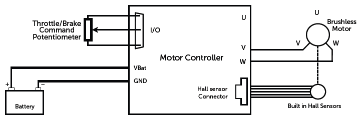
As an example, motor controllers from Roboteq are capable of sensing the rotational speed of the motor. On brushless motors, this is done without any additional hardware by monitoring the changes of the motor’s hall sensors. On brushed dc motors, speed can be sensed using an optical encoder mounted on the motor shaft. Applying 50% power and recording the speed of the unloaded motor gives the ability to know what power level is necessary to approach the motor’s BEMF.
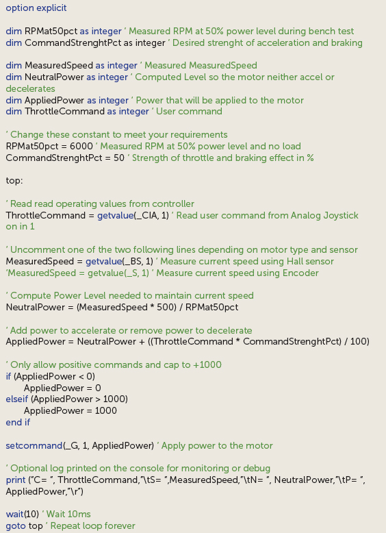
Using the controller’s Microbasic scripting language, we can easily write a script that will measure the motor’s current speed and compute the power level that must be output to accelerate, brake, or maintain the current speed.

For example, consider the case of a vehicle where at 50% PWM, the motor turns at 2,500 RPM when the wheel is not touching the ground.
If the vehicle is now on a slope where the motor is spinning at 2,500 RPM, the controller will measure the RPM and will apply 50% power to it, and so it will consume practically no current (current will be the no-load current at that speed). This is because when on a slope that makes the motor run naturally at 2,500 RPM, the electromechanical conditions are exactly the same as when the wheel is not touching the ground.
Now, if we apply more than 50% power while the motor already spins at 2,500 RPM, this will give extra power and the motor will try to run faster.
If we apply less than 50% power while at 2,500 RPM, there will be regenerative braking. The lower the controller output is, the stronger the braking.
The technique is therefore to let the controller measure speed, compute the power output to apply to it to neither accelerate nor brake at that RPM, then use the throttle command to increase or lower that power level in order to either accelerate or brake.
Configuring, testing and improving the script
To use the script [see “Script” below], it’s first necessary to measure the RPM reported by the controller at 50% power level. Then enter this value as a constant in the top part of the script. Then with the command joystick centered and the script running, the motor will remain idle. Turning the motor shaft by hand will result in power being applied to the motor and it will have almost no resistance in the forward direction.
The script below is the complete listing needed to achieve controlled regeneration. It uses a single user command for throttle and brake. This script is also written to operate the motor only in the forward direction.

Then applying the joystick command in the forward direction, the motor will accelerate and brake when the joystick is in the reverse direction. The amount of acceleration and braking for a given joystick position can be adjusted by changing another constant in the script.
The script assumes a stable voltage is present at the battery so that a given power level will always result in the same output voltage equivalent. For example, with 24 V, 50% RPM will result in 12 V at the motor. If it is expected that battery voltage will fluctuate significantly, the script should be modified to take account of the battery’s current voltage. For example, to still have 12 V at the motor while the battery is 18V instead of 24 V, the power level must now be 75% instead of 50%.
The script can also easily be modified to use a separate throttle and brake pedal by capturing two analog inputs and computing a resulting command depending on how hard each is pressed, and prioritizing the brake over the throttle, for example. The strength of the braking can also be made to be higher or lower.
When very strong braking is required, the script can be modified to activate an electromechanical brake connected to one of the controller’s digital outputs.
Benefit compared to other controlled regenerative braking techniques
For all practical purposes, this technique that uses the motor’s measured actual speed to compute its BEMF results in drive characteristics that are similar to torque mode drive, where the controller will attempt to feed the motor with constant current.
Compared to torque mode, the method described here is more accurate because it’s typically simpler and more accurate to measure speed than it is to measure motor current. Most motor controllers, including Roboteq’s, measure the battery current whereas it’s the motor current that must be regulated in torque mode. Motor current is approximated from the measured motor current and will be very inaccurate at low power levels. Motor current cannot be measured at all when the power level is 0.
In addition, in torque mode, the controller uses a regulator, typically PID, that will continuously adjust the power level in order to move the measured current to the desired value. The PID needs tuning which is not always simple given the variable load condition of a motor in transportation applications. The control loop continuous “guessing” is not as quick or accurate as the immediate computation of the motor’s BEMF from the measured speed.
Roboteq, Inc.
www.roboteq.com


Leave a Reply
You must be logged in to post a comment.