• Skip to primary navigation
  • Skip to main content
  • Skip to primary sidebar
  • Skip to footer

Motion Control Tips

Automation • Motion Control • Power Transmission

  • News
    • Industry News
    • Editor Blogs
    • Video
  • Controls
    • HMIs
    • PC-Based Controllers
    • PLCs + PACs
    • Stand-Alone Controllers
    • Software
  • Drives
    • Servo Drives
    • Stepper Drives
  • Encoders
    • Absolute Encoders
    • Incremental Encoders
    • Rotary Encoders
  • Mechanical
    • Bearings
    • Brakes + Clutches
    • Belt + chain
    • Couplings
    • Gears + Gearing
    • Lubrication
    • Shock + Vibration Mitigation
    • Springs + Rings + Seals
  • Linear
    • Actuators
    • Linear Motors
    • Linear Encoders
  • Motors
    • AC Motors
    • DC Motors
    • Brushless Motors
    • Gearmotors
    • Piezo Motors
    • Servo Motors
    • Stepper Motors
  • Systems
    • Conveyors + linear transport systems
    • Gantries + Stages
    • Rotary Tables
    • Grippers + End Effectors
    • Robotics
  • Networks
    • Connections + Sliprings
    • Fieldbuses
    • I/O
    • Sensors + Vision
  • FAQs
    • Motion Casebook
    • Motion Selection Guides
  • Suppliers
You are here: Home / Mechanical PT / Couplings / What are bellows couplings? Technical summary for design engineers

What are bellows couplings? Technical summary for design engineers

October 6, 2011 By Motion Control Tips Editor Leave a Comment

Bellows couplings are one form of flexible coupling with twin coupling ends called hubs capping a precision-engineered corrugated tube that serves as the coupling body.

Bellows couplings are known for their exceptional torsional rigidity to accurately transmit velocity, angular position, and torque. Their slight flexibility (at the corrugated bellows) serves to address limited amounts of axial, angular, and parallel misalignment between the shafts or other components being joined.

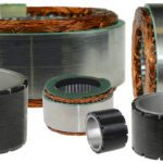
Bellows couplings are typically made from a stainless steel tube that is hydroformed (or in some cases welded) to create deep corrugations. Such hydroformed bellows begin as a sheet of stainless steel or other metal. This sheet is draw into a a tube which it then pressurized from within against a ribbed die to form a corrugated shape. Then the end hubs are welded or bonded in some manner to this coupling bellows.


Bellows couplings tend to have the highest torsional stiffness of any servo motor coupling, and so are used in applications requiring high precision positioning.

what are bellows couplings
Bellows couplings absorb slight misalignments from perpendicularity and concentricity tolerances between the mounting surfaces of the two connected components.

Selecting the right bellows coupling for an application starts with knowing the torque involved. For instance, it’s helpful to know the peak torque capacity of the servo motor. This value, multiplied by the gear reduction ratio and a safety factor of 1.5, gives the minimal torque calculation.

In most cases, couplings are rated according to the maximum peak torque to be transmitted. The peak torque should not exceed the coupling’s rated torque. Rated torque is a term that refers to the torque that is continuously transmittable within the specified acceptable speed and misalignment ranges. Learn what a bellows coupling torque failure look likes in this article here.

Other applications where bellows couplings excel

Unlike some couplings that include polymer inserts or other elements (usually to impart some misalignment or vibration compensation) all-metal bellows couplings excel in very hot environments. They also find use on precision equipment having components that may exhibit dimensional changes (and inducing axial misalignment) when subject to fluctuating temperatures.

The partially hollow construction of bellows couplings makes them lighter and indispensable on axes needing a train of power-transmission components with the lowest possible moments of inertia. Such applications include servomotor-driven designs that need to be nimble and quickly accelerate and decelerate. Here, the high torsional stiffness exhibited by bellows couplings is also useful — especially where an axis must make quick indexing or reversing moves.

You may also like:

  • frameless motors
    Drives and controls for robotics: See them at the 2019…

  • Mach III Clutch Inc. supplies mechanical friction torque limiter for…

  • Video on torque limiters: Examples of how to customize for…
  • couplings
    Dual-keyed rigid couplings prevent axial and radial slippage

  • 12 Motion Trends articles offer engineering insight and technical 411

Filed Under: Couplings, FAQs + basics, Mechanical PT

Reader Interactions

Leave a Reply

You must be logged in to post a comment.

Primary Sidebar

POWER TRANSMISSION REFERENCE GUIDE

DESIGN GUIDE LIBRARY

“motion
Subscribe Today

RSS Featured White Papers

  • Specifying electric rodless actuators: Ten tips for maximizing actuator life and system performance
  • The truth about actuator life: Screw drive survival
  • Top Ten Tips: How to specify electric rod-style actuators for optimal performance, reliability and efficiency

Footer

Motion Control Tips

DESIGN WORLD NETWORK

Design World Online
The Robot Report
Coupling Tips
Linear Motion Tips
Bearing Tips
Fastener Engineering.

MOTION CONTROL TIPS

Subscribe to our newsletter
Advertise with us
Contact us
About us
Follow us on TwitterAdd us on FacebookAdd us on LinkedInAdd us on YouTubeAdd us on Instagram

Copyright © 2022 · WTWH Media LLC and its licensors. All rights reserved.
The material on this site may not be reproduced, distributed, transmitted, cached or otherwise used, except with the prior written permission of WTWH Media.

Privacy Policy | RSS