 By Jeff Smoot, VP Motion Control, CUI Inc.
Capacitive commutation can speed up the assembly of brushless dc motors and be more accurate than conventional Hall sensors.
Examine a cordless power tool or a computer hard drive and you’ll likely find a brushless dc motor (BLDC) doing the work. BLDCs have become widely used in recent years because of their high torque and simple topology that eliminates the need for graphite brushes that commutate power to the motor windings.
BLDC motors replace brush commutators with sensors and switching electronics that perform the same function. Therein lies a potential problem: It can be time consuming to set up and align the sensors necessary for commutation.
However, recent advances in sensing technology have simplified the commutator setup process. Specifically, rotary encoders based on a capacitive sensing principle can sense rotor position for commutation purposes. These sensors are simpler to setup than the Hall effect sensors that are traditionally used for commutation. They also hold advantages over sensorless methods sometimes used for commutation. To understand why, we’ll review a few basic ideas of BLDC commutation and explain how capacitance can serve as a mechanism for sensing motor shaft position.

Basics of commutation
As a quick review, the windings of BLDC motors are distributed about the stator such that they are energized in sequence to rotate the rotor shaft. The most common BLDC configuration usually employs three stator phases separated from each other by 120 electrical degrees. The motor drive generates voltage waves applied to the active phases of the winding system so the angle between the stator flux and the rotor flux stays close to 90°, a condition necessary to generate maximum generated torque. Thus, the controller needs some means of determining the rotor orientation relative to the stator coils.
The traditional means of sensing rotor orientation has been with Hall-effect sensors mounted in the air gap between the rotor and stator. Three Hall sensors (for a three-phase motor) detect the magnetic field of the passing rotor magnets. Each sensor outputs a high level for 180° of an electrical rotation and a low level for the other 180°. The three sensors have a 60° relative offset from each other. The process of switching the current to flow through only two phases for every 60 electrical degrees of rotation is called electronic commutation. In the most common case, a three-phase inverter powers the motor, and the switching actions are triggered by the signals from the Hall sensors. When the sensors are aligned properly, their outputs can be decoded into the necessary three-phase switching sequence.

The number of electrical cycles repeated to complete a single turn of the rotor shaft is determined by the number of rotor pole pairs. One electrical cycle completes for each rotor pole pair. The number of electrical cycles/rotation equals the number of rotor pole pairs.
However, it may be possible to eliminate the need for commutation sensors in some applications when the BLDC isn’t used for positioning. In sensorless commutation, special algorithms measure the motor back EMF as an indication of rotor position. One caveat is that this scheme is most effective when the load varies only slowly or not at all, or at least changes in a predictable way.
Sensorless commutation uses the fact that in the excitation of a brushless motor, not all of the phase windings conduct simultaneously. The nonconducting windings carry a back EMF. Moreover, there are slight differences in inductance of each stator phase. Thus, there are variations in the current each phase carries. This variation of current responses contains information about the rotor position, which can be used for commutation.
For example, one of the simplest methods of back-EMF sensing is based on detecting the instant at which the back EMF in the unexcited phase crosses zero. This zero crossing starts a timer used to trigger the next sequential inverter commutation so it takes place at the end to the timing interval.
Of course, there are complications with the back-EMF approach that limit its use. One is that the back EMF is proportional to speed. Thus, back EMF is zero when the motor is at standstill so there is no back EMF to sense. Similarly, it may be tough to sense rotor position when back EMF crosses zero at low speeds, hampering the performance of this approach. There are ways around these difficulties, but sensorless commutation today has applications limited to those that don’t involve positioning. It also remains a research topic.
Comparing sensor-based commutation setups
BLDC motors using a sensor-based approach for commutation may or may not do so using Hall effect sensors. Sometimes commutation can take place using a commutation track on the motor encoder. The commutation track has outputs that mimic signals that would be obtained from Hall sensors.
Also recall that common three-phase motors typically use three Hall devices positioned 120° apart to align with the three motor phases. Nominal accuracy of a Hall device is ±1 to 3°. But the accuracy of Hall devices becomes a potential problem with high-pole-count motors where the ratio of electrical degrees to mechanical degrees rises with the pole count. While there are never more than 360 mechanical degrees in every revolution, the number of electrical degrees is the product of 360 times the number of pole pairs. The nominal accuracy of the Hall device degrades with a greater number of poles. This is critical because accuracy of the commutation timing affects motor efficiency.
Thus, Hall devices work best with low-pole-count motors typically used in high-speed, low-torque applications. High-pole-count motors are slow, high-torque devices. They are not good candidates for Hall commutation because they suffer significant energy loss as commutation signal accuracy degrades.
Regardless of pole count, Hall devices must be accurately positioned in the motor housing. In cases where the Hall sensor alignment is optimized manually, the optimization process can be time consuming. It generally involves use of a second motor to turn the primary motor while a technician displays a back EMF signal on a scope, checking to see if the zero-crossing point of the sinusoidal waveform corresponds to the rising edge of the U commutation signal. This tends to be an iterative process.
While hall devices are much less expensive, the considerable alignment time adds labor cost. The extra cost generally results in the end product being more costly than one that includes the encoder.
Another method used to commutate current to BLDC motors is with an encoder. Optical encoders, for example, are much more accurate than Hall devices, but they also cost more. An additional benefit of an encoder are the generation of incremental encoder outputs that can be used elsewhere in the motion control system for location, speed, distance calculations.
With encoders, the commutation signals are generated by a pattern etched on the glass or metal disc inside the encoder. However, commutation signals generated this way are only applicable to one motor configuration. They must be optimized for the motor in question. And there is some care involved in mounting the encoder. Finger oils left on the disc can deflect light and cause subsequent data errors. A back EMF fixture is also required for aligning and checking the encoder alignment. Finally, the mechanical alignment of the encoder with the motor shaft position typically involves visually tracking a mechanical zero-position mark on the encoder hub or electrical tracking through an oscilloscope. Either method can be time consuming.
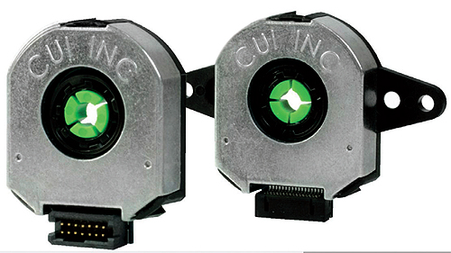
In contrast, capacitive rotary encoders used for commutation can be more accurate than Hall effect sensors, less expensive than optical encoders, and much more rugged than the opticals. The setup process of mating them to the motor and aligning is simplified by the use of a microcontroller and built-in ASIC that digitally sets the zero position, pole count and commutation angle.
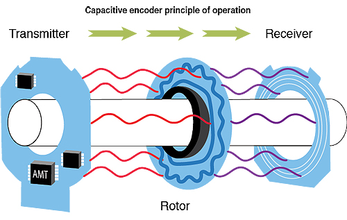
To read shaft position, a capacitive transducer uses an encoder disk that modulates the capacitive coupling between electrodes on a transmitter disk and a receiver disk. Conductive segments on the rotating disk couple high-frequency (about 10 MHz) signals between the transmitter and receiver boards. The relative amplitude of signals coupled from different parts of the transmitter board depend on the position of the disk and so serve as a means of measuring the shaft position. An ASIC uses this amplitude information to compute the sensor position for each measurement cycle. Additional computations on the ASIC create a continuous model of the rotational motion and derive quadrature signals similar to those from optical encoders.
Specifically, a synchronous detector and low-pass filter at the receiver strips away the 10-MHz carrier and leaves the amplitude modulation, resulting in a signal that is effectively sinusoidal at about 10 kHz. Its phase is a measure of the angular position of the encoder disk. Other circuitry on the receiver detects the zero crossings of this signal. The resulting information is used to note the count at the time of the zero crossing. The count becomes a digital measure of the angular position of the encoder disk and thus generates the digital representation of the shaft position.
The specially designed ASIC chip can also adjust the quadrature resolution among 16 different values from 2,048 to 48 ppr.
A final point to note is that the capacitive encoder generates its commutation signals by parsing its 4,096 absolute positions to accommodate the number of pole pairs programmable by the user. This offers a broader flexibility in motor choice with higher switching accuracy not available with optical encoders.
Reprint info >> || CUI Inc. www.cui.com


Leave a Reply
You must be logged in to post a comment.