
by Steven Peterson, Product Training Engineer, Yaskawa America
Deciding which setup is right for a common bus takes research and evaluation, but selecting and implementing the right one significantly improves design performance and efficiency. Here we’ll outline how to prioritize features while accommodating a given design’s potential amount of regenerative energy and harmonic content.
Designers implement VFDs on a variety of applications due to their high performance, reliability and energy savings. However, VFDs are not without shortcomings.
On most VFDs, the input diode bridge consists of six diodes. These diodes make up the converter portion of a VFD and rectify the three-phase ac input to a fixed dc voltage. Current flow in the converter portion is typically unidirectional. This is a non-issue in most applications, but causes problems when an application has regenerative energy present—for example, when a motor is braking or overhauling due to the load. Such situations cause the motor to act as a generator sending energy back into the VFD. Here, the diode bridge stops current from flowing back to the line; that charges the dc bus capacitors and potentially causes faults due to high dc bus voltage.
In this article, we’ll compare various solutions that use line regeneration and common dc bus arrangements. Then we’ll detail solutions with different benefits (including more compact designs, cost reduction, energy savings and reliability improvements).
Common dc bus
Applications consisting of just two VFDs can benefit from a common dc bus, sometimes called a shared bus. Simply interlinking the dc bus between VFDs through a fused connection establishes a common bus.
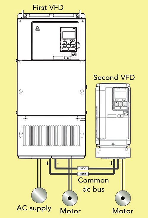
The key benefit of a common bus is the sharing and balancing of power. For example, consider a system with two VFDs and two motors: One motor may be in a motoring state while the other motor is in a regenerating state. During this condition, the motoring VFD consumes the regenerative power instead of pulling from the grid.
Some notes here: Remember that two common conditions that can cause regeneration are an overhauled motor or when a motor is braking. Also: Regenerative energy is sometimes called braking energy. However, for simplicity in this article, we’ll just use the term regenerative.
There are multiple ways to establish a common dc bus, each with its own strong points. However, there is no sole best method, as applications can vary wildly and all applications feature differing system needs and budgets.
One quick note on terminology: Motoring is when an electric motor is converting electrical energy into mechanical energy to perform work; regenerating is when a motor is overhauling or braking, it acts such as a generator. Mechanical energy generates electrical energy.
Six-pulse diode bridge rectifier
One option is for the design to use a large stand-alone six-pulse diode bridge rectifier to establish a common bus. The diode bridge serves to rectify the ac input power to dc. The diode bridge must be of an appropriate size to power all connected VFDs and loads. The diode bridge is identical to the converter section of many VFDs. It’s inherently unidirectional, meaning that excess regenerative energy cannot be sent back to the grid.
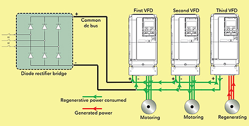
Motoring loads must be greater than regenerating loads to keep the dc-bus voltage at a safe level. When regenerating loads are greater than motoring loads, the design must implement a common dynamic-braking package or line regeneration. Alternatively, when the amount of regenerative energy present is low, wiring is simple and less complicated than that of a standard ac setup.
Another option: Line regeneration
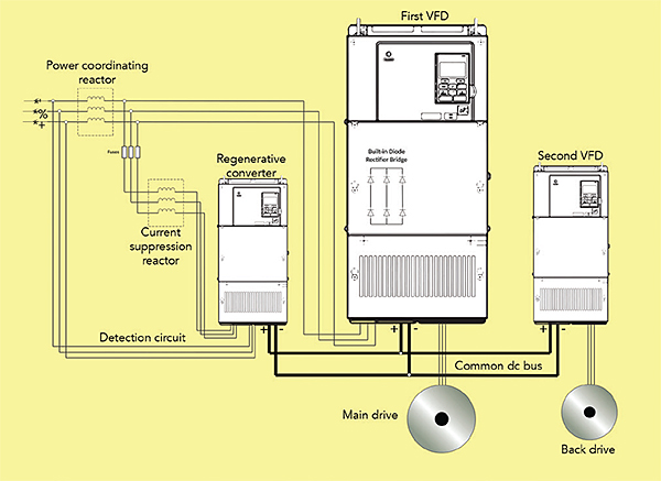
If an application needs to return excess regenerative energy to the grid, line regeneration is an option. Here, the electrical system sends excess regenerative energy back to the line by line regeneration. To accomplish this, the design must implement a regenerative converter. This converter wires into the common dc bus just like the existing drives. This converter accepts excess dc voltage from the bus and outputs a six-step waveform back to the grid. This reduces operating costs due to recycling of the regenerated power back to the supply. Total regenerative energy present dictates the capacity of the regenerative converter.
Instead of using a stand-alone diode-bridge rectifier to provide a system with dc power, it’s sometimes beneficial to use a larger VFD. A VFD has a built-in rectification circuit on its front end. Engineers can establish a common bus by sizing the VFD to supply dc power onward to connected VFDs and motors.
Note that, compared to a six-pulse diode rectifier, this setup eliminates the stand-alone rectifier, as the second VFD gets power from the dc bus of the first one. This makes one wiring simpler while keeping costs down.
An industrial centrifuge is one design that benefits from a common dc bus.
A centrifuge consists of a main drive, which turns the drum, and a back drive, which turns the auger at a speed slightly slower than the drum to separate fluids or solids. The back drive is typically a smaller capacity than the main drive. In this application, the back drive is in constant regeneration because it is acting as a brake. This braking energy can power the main drive that’s motoring. When the main drive needs to stop, there’s huge inertial load present. This makes regenerative energy excessively high during deceleration and warrants the need to send the power back to the grid through a regenerative converter.
Cost and space requirements are always a top priority. These are directly proportional to the amount of regenerative energy present. So, it’s extremely important that an engineer confirms the amount of regenerative energy on a given application. Knowing this, the engineer can either opt to oversize the larger VFD to increase bus capacity or use a regenerative converter to apply energy back to the grid. If the amount of regeneration taking place is low, a dynamic braking setup is the most cost-effective solution. Dynamic braking simply burns off the excess voltage onto a bank of resistors.
If the design engineer determines that a regenerative converter is necessary, take note of the additional devices when using it. The reactors are necessary to limit current supplied back to the grid and add impedance between the ac source and load devices. There is also a detection circuit, which is wired directly from the converter to the power supply. The converter uses this circuit to detect the power supply phase order and voltage levels. Tip: Whenever designers consider a common dc bus or line regeneration, follow manufacturer wiring requirements for each system device. Pay particularly close attention to fusing recommendations, peripheral devices, power up sequencing and maximum lengths for dc bus lines.
Harmonics and active front ends
The input diode bridge on a VFD conducts the line current in a discontinuous (non-linear) fashion. This is due to the input diodes only conducting during the peak voltage amplitude of each input phase. The result is a rippled voltage waveform, in turn causing input current distortion and harmonics applied back to the supply.
A regenerative converter always wires in parallel to the VFDs on a common bus. The VFD diode bridge is not isolated from the supply, so the converter won’t help mitigate harmonics generated by the diode bridge. Typically, when harmonics are a concern, the design implements passive front ends consisting of various reactors, filters and multi-pulse transformers. These decrease harmonics but cannot handle line regeneration. Additionally, passive front ends tend to be both expensive and bulky.
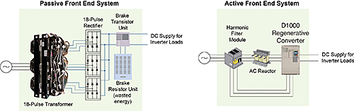
A regenerative active front end (AFE) is implemented when harmonic mitigation and line regeneration are a concern. A regenerative AFE gets wired in series with the VFDs being powered from it. Harmonics are low due to passive filtering and reactors paired with the AFE in combination with a pulse-width modulated (PWM) switch array on the input of the front end. Fly-back diodes on the insulated gate bipolar transistors (IGBTs) rectify ac-to-dc for powering one or multiple drives. Additionally, the IGBTs use PWM to reconstruct an ac sine wave by switching the dc bus voltage back onto the supply when regenerative energy is present, making the AFE bidirectional.
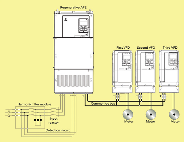
connected to it. This arrangement is useful in that it reduces harmonics, simplifies wiring and offers line regeneration.
Sizing a regenerative AFE is a matter of simple addition. First, add up all VFD capacities to be powered by the AFE. For example, consider an application running four 45-kW VFDs. To determine which size of regenerative AFE to select, we calculate that 45 kW x 4 = 180 kW. So using simple math, we find that the AFE must be rated for at least 180 kW. The application needs this rating because the AFE works as a power supply for all connected VFDs. This differs from the regenerative converter mentioned earlier (sized solely on the amount of regenerative energy present).
Yaskawa
www.yaskawa.com
Leave a Reply
You must be logged in to post a comment.