Charan Bhamra
Mechatronics Engineer
EZmotion
For engineers and designers working on modern-day motion and other industrial applications, it’s vital to understand the advantages and disadvantages of stepper and brushless dc (BLDC) motors. Here we’ll look at a widely used hybrid stepper motor and a 3-phase BLDC motor and compare both devices. We’ll consider the working principles of these motors (physical size and power density) and make observations about the acceleration and noise aspects of each motor. Experiments performed under various load conditions reveal changes in power, efficiency, and temperature.
Stepper motors
Most widely used stepper motors are hybrid stepper motors, which consist of permanent magnet rotors and electromagnet stators. Rotors have two cups with permanent magnets: one with north poles, and a second with south poles.
A simplified stepper motor has a rotor made of two cups of permanent magnets. Each cup has three teeth with a respective magnet pole. In this case, these cups are assembled such that they are out of phase by a half-pitch (60°). The stator consists of four poles with two phase windings.
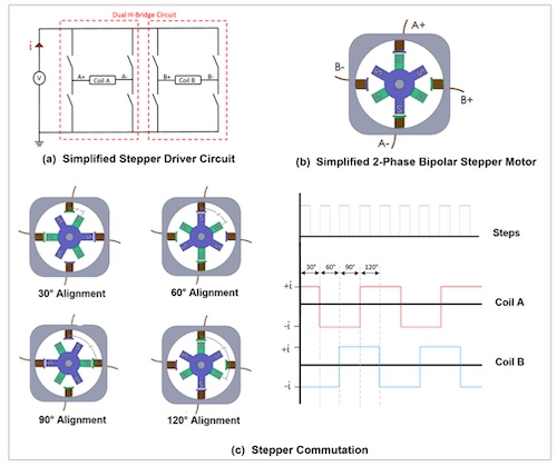
Steppers are electronically commutated. According to step input pulses, the bipolar stepper driver uses a dual H-bridge circuit to energize the stator poles in a sequence that allows the rotor to rotate by a step angle. The step angle can be calculated with Equation (1):
(1) Step Angle (in °) = 360/(2 x (n_ROTORTEETH)(n_PHASE))
For each step pulse, the rotor rotates 30° — this stepper is known as a 12 full-step stepper motor. During full-step operation, the commutation sequence and rotor position follow a particular sequence. Most stepper motors on the market have 50 or 100 pole pairs, with 200 or 400 full steps for one full rotor revolution. This makes the step angle as small as 1.8° or 0.9°.
With an advanced stepper motor driver, this small step angle can be further divided into even smaller angles by implementing microstepping operation. The step angle can be reduced by a half-step, quarter-step, and up to a 1/256 step. Stepper motors offer superior positional accuracy because they can step by such small angles.
Brushless dc (BLDC) motors
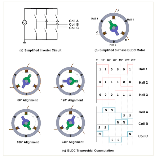
Brushless dc motors have a permanent magnet rotor and electromagnet stator and require electronic commutation. To commutate brushless dc motors, the instantaneous position of the rotor is required. To meet this requirement, Hall-effect sensors are used to realize the rotor’s angular position. This information is fed to a microcontroller (MCU) that switches the phase winding current using the 3-phase inverter circuit. Essentially, the dc input voltage is converted to 3-phase ac voltage to sequentially energize the stator poles using an inverter circuit.
The rotor magnetic field always chases the stator magnetic field, which results in BLDC motor spinning. Since the simplified motor is a single pole pair BLDC, each commutation step is 60 electrical and mechanical degrees. BLDC trapezoidal commutation and the rotor position can be obtained. However, typical trapezoidal commutation makes the motor susceptible to torque ripples. As a result, an advanced commutation called field-oriented control (FOC) is used on the BLDC for testing. FOC provides minimal torque ripple and smooth motor operation.
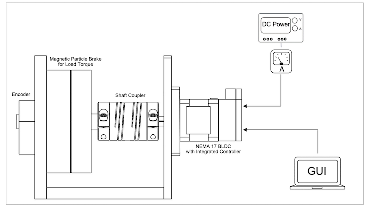
Experimental set-up
Stepper motor test
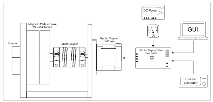
To set up the stepper motor test, a NEMA 23 bipolar stepper motor is used along with a magnetic particle brake for load simulation. The motor test requires five main components described below:
- An encoder (mounted on the particle brake’s other end) monitors the shaft’s rotational speed.
- A bipolar stepper motor driver — featuring parallel inputs, internal current sensing, and regulation — controls the stepper motor.
- A 24V dc bench supply placed in series with a current meter measures the dc current draw of the stepper motor under different load conditions. In addition, the 24V dc bench supply powers the stepper motor driver.
- The motor driver’s MotionLAB, which is compatible with the serial peripheral interface (SPI), configures the stepper motor driver’s parameters, such as the step mode, rated current, and additional motor settings.
- A function generator sends square pulses to the driver, which drives the motor forward.
Brushless dc motor test
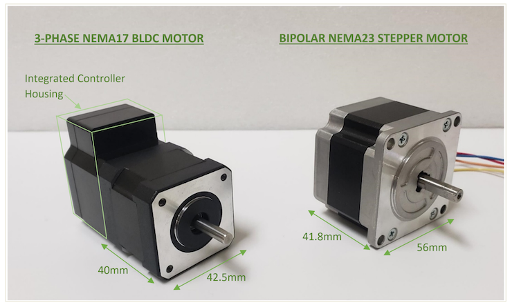
Similar to the stepper motor test, the brushless dc motor test set-up includes a magnetic particle brake for load simulation, as well as a NEMA 17 BLDC motor with an integrated controller.
To power the controller, a 24V dc bench supply is used in series with a current meter to measure the dc current draw of the brushless dc motor under different load conditions. Then the MotionLAB GUI can drive the BLDC in speed control mode for this test.
Current draw comparison
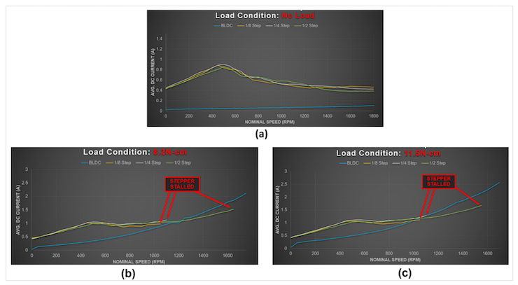
Steppers typically operate under constant current, otherwise known as constant torque. This forces steppers to always draw the maximum current, regardless of the load on the motor shaft. As a result, steppers can provide maximum torque across the low-speed range. However, this also leads to large amounts of wasted energy in the windings in the form of heat.
In this experiment, the stepper motor was tested in three microstepping resolutions: half-step, fourth-step, and eighth-step. The dc current draw was recorded at various motors speeds under three different load conditions (no load, 8.2 N-cm, and 11.5 N-cm). The experimental results demonstrate the stepper motor’s less efficient measured dc current draw compared to a BLDC motor.
The no-load current draw was also measured for the brushless dc motor, half-step stepper motor, fourth-step stepper motor, and eighth-step stepper motor. The stepper motor draws a significantly higher zero-speed current than the BLDC, even when there is no mechanical operation. Furthermore, the stepper motor current draw remains high across the low-speed range. As the motor speed increases to the high-speed range, the stepper motor’s current draw begins to decrease due to the inductance of the motor windings and back EMF.
Next, the current draw was measured for the BLDC motor, half-step stepper motor, fourth-step stepper motor, and eighth-step stepper motor when there is some load added on the shaft. The stepper motors stall at high speeds because they have less current in the windings. Although microstepping increases the motor’s positional resolution, it also decreases the output torque. The eight-step and fourth-step stepper motors stalled at the mid-range speed as well. Meanwhile, the BLDC motor only draws what it needs depending on the shaft’s load.
Under no-load conditions, the BLDC draws a small current to rotate the rotor. At the same time, the current draw increases if load is added to the shaft, allowing the BLDC motor to continue spinning at a higher speed than the stepper motor. Therefore, BLDC motors are more power-efficient compared to stepper motors due to their ability to draw current based on the load.
Power density comparison
Power density is a measure of motor output power per unit volume. Brushless dc motors typically have higher power density compared to stepper motors.
Using these dimensions, the volume can be estimated as 73 cm3 for the BLDC motor and 131 cm3 for the stepper motor. A motor’s output power is equal to the output speed multiplied by the output torque. The BLDC motor continues to spin at a higher speed compared to the stepper motor under the same load conditions, which means that the BLDC motor provides a higher power density, since it has a higher power output with a smaller. Power density plays an important role in applications with limited available space and a high power requirement, such as drones and quadcopters.
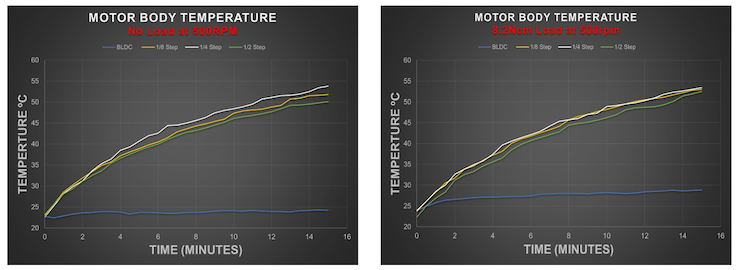
Temperature rise comparison
As discussed previously, constant current operation for the stepper motor leads to major energy losses in the windings, mainly in the form of heat. During the experiment, the motors’ body temperature was measured in an ambient temperature of 22°C.
The stepper motor’s temperature rises steadily regardless of the load on the shaft. In comparison, the brushless dc motor’s ability to not draw excessive current means the body temperature only increases minimally. Unlike stepper motors, BLDCs convert a high percentage of input power into mechanical power instead of heat.
Acceleration and noise comparison
The high pole count of steppers is directly responsible for their superior positional accuracy over BLDCs. However, the high pole count also results in limited acceleration and high audible noise during operation. Accelerating a stepper motor can be difficult since it requires a gradual ramping of motor speed to sustain the shaft’s angular positional accuracy. If a stepper accelerates quickly, then it faces the risk of missing steps, which can cause issues in many applications. In addition, if there is low input current combined with high acceleration demand, then the stepper may stall.
In terms of noise, brushless dc and stepper motors can detect a particular torque, otherwise known as cogging torque, which causes vibrations and ringing at every step of the stepper motor rotation. Because the BLDC current draw is proportional to the load on the shaft, BLDCs can draw the additional current required to accelerate the load within the motor’s rated speed range. BLDCs are much quieter during normal operation than steppers. Therefore, BLDC motors are reliable and efficient solutions that offer high speed, high acceleration, and less audible noise.
Conclusion
While the positional accuracy of BLDC motors is proportional to the angle sensor accuracy, integrated BLDC motors with a high-resolution angle sensor can offer exceptional positional accuracy. With microstepping, stepper motors offer superior positional accuracy over brushless dc motors. This comes with the disadvantage of offering less torque beginning from mid-range speeds, which lead to missing steps or stalling. Steppers lack the ability to quickly accelerate, and they produce more noise than BLDCs. Overall, stepper motors are a less expensive solution, but they are limited to low-speed applications. BLDC motors are dependable, quieter solutions that offer higher efficiency and accuracy across a wide speed range.
EZmotion
ezmotion.co
Leave a Reply
You must be logged in to post a comment.