• Skip to primary navigation
  • Skip to main content
  • Skip to primary sidebar
  • Skip to footer

Motion Control Tips

Automation • Motion Control • Power Transmission

  • News
    • Industry News
    • Editor Blogs
    • Video
  • Controls
    • HMIs
    • PC-Based Controllers
    • PLCs + PACs
    • Stand-Alone Controllers
    • Software
  • Drives
    • Servo Drives
    • Stepper Drives
  • Encoders
    • Absolute Encoders
    • Incremental Encoders
    • Rotary Encoders
  • Mechanical
    • Bearings
    • Brakes + Clutches
    • Belt + chain
    • Couplings
    • Gears + Gearing
    • Lubrication
    • Shock + Vibration Mitigation
    • Springs + Rings + Seals
  • Linear
    • Actuators
    • Linear Motors
    • Linear Encoders
  • Motors
    • AC Motors
    • DC Motors
    • Brushless Motors
    • Gearmotors
    • Piezo Motors
    • Servo Motors
    • Stepper Motors
  • Systems
    • Conveyors + linear transport systems
    • Gantries + Stages
    • Rotary Tables
    • Grippers + End Effectors
    • Robotics
  • Networks
    • Connections + Sliprings
    • Fieldbuses
    • I/O
    • Sensors + Vision
  • FAQs
    • Motion Casebook
    • Motion Selection Guides
  • Suppliers
You are here: Home / FAQs + basics / What are Grippers and End Effectors? Technical Summary

What are Grippers and End Effectors? Technical Summary

August 25, 2013 By Motion Control Tips Editor Leave a Comment

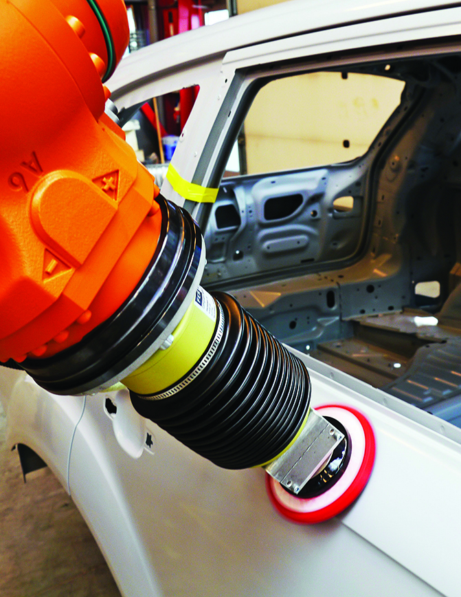
Updated December 2015 by Lisa Eitel || In robotics and material handling, end effectors are tools or devices connected to the end of a robot arm that accomplish some task. End effectors can be a range of types, including cutting tools and drills, welding tools, brushes, screwdrivers, vacuum cups and grippers.

Shown here are PB swing-arm and PEC arm over-clamps from PHD, Inc. working to hold ATV frame components together in a robotic-welding application.

Grippers are devices often used with pick-and-place robotic systems to pick up or place an object on an assembly line, conveyor system or other automated system. Fingered tooling or jaws are attached to grippers to grip or hold the object. Recently, robotic grippers have made headlines, thanks largely to breathtaking new prosthetics, smarter material-handling machines and fairly brisk robotic innovation.

Here, a sensor-feedback flange from KEBA Corp. (called the Active Contact Flange) helps a robot arm buff an auto body with enough precision to ready the surface for a smooth coat of paint. Such end-effector fixtures are increasingly common on six-axis robot arms.

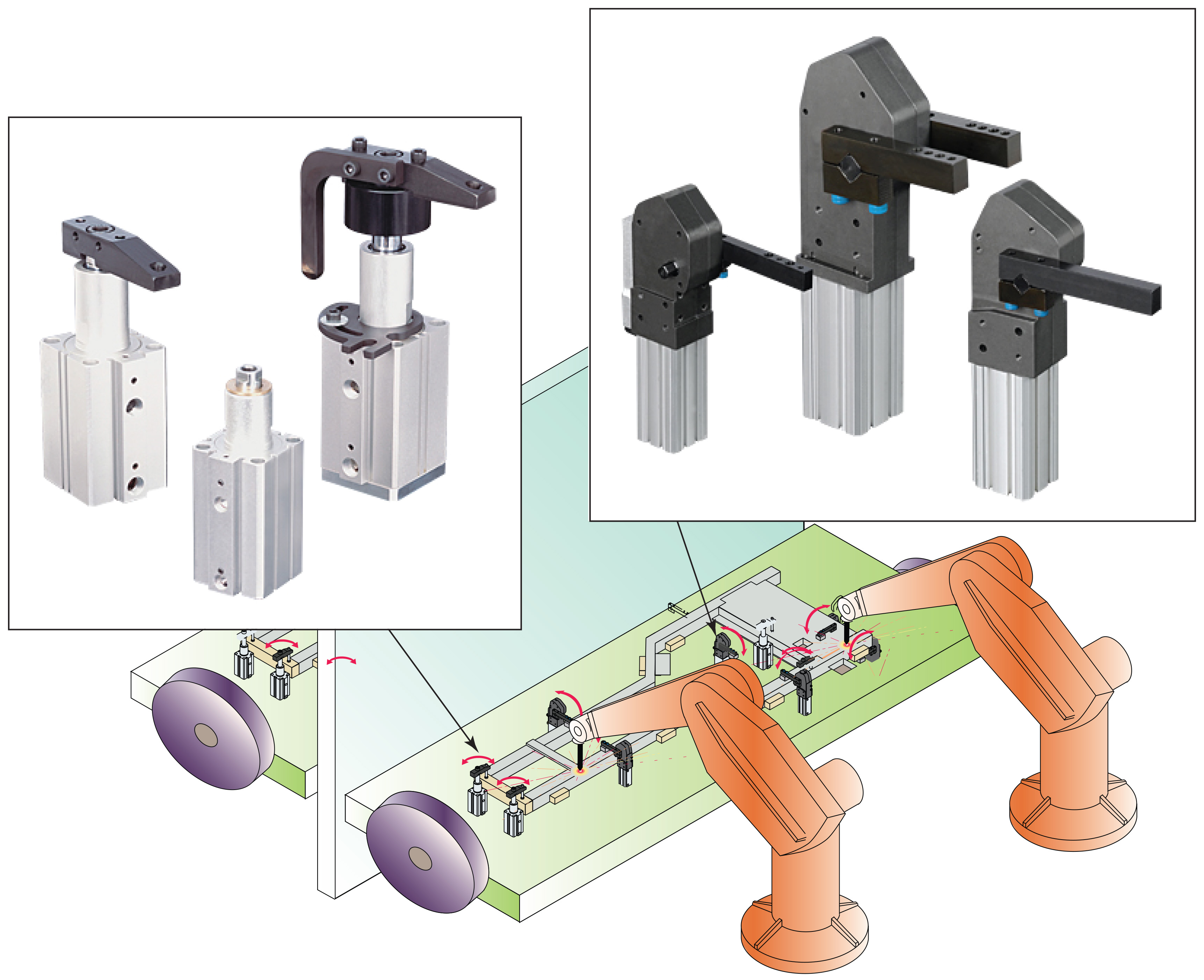
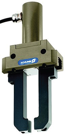
Grippers come in a variety of styles and powered designs. Three common types are parallel, three-finger and angled designs. The most common are parallel designs with two fingers that close on a workpiece to grip it or open it out by creating pressure on the inside. Three-finger designs hold the workpiece in the center, and have three fingers offset by 120°. Finally, angled designs feature jaws that work at a variety of different angle openings.

This Z-theta system is from Haydon Kerk motion system integrator Catalyst Motion Group. Z-theta systems offer a compact and effective package for a rotary axis and a linear axis in a single unit that work concurrently to output a helical motion path. Z-theta systems can also move to defined linear positions, then perform independent rotary moves. Loads of up to 100 lb and speeds in excess of 10 in./sec are possible.

Ultimately, it’s the size, force and shape of the parts that the machine must grip that dictate the most suitable gripper style. For today’s industrial applications, gripper designs are increasingly diverse. Other grippers that don’t fall into neat categories include single-jaw grippers, bladder grippers that inflate against part ODs and IDs, and magnetic grippers.

Here, a Yaskawa Motoman arm does unstructured depalletizing using Universal Robotics’ flagship machine-learning software, Neocortex. The software is an interactive 3D learning platform that leverages sensor inputs to learn and react in real time. Note the Schmalz pneumatic gripper array at the arm’s end.

In addition, three choices of power are available, the most common being pneumatic power and the least common being hydraulic designs. Traditional pneumatic grippers still dominate industrial-assembly and robotic applications. That’s because pneumatic grippers are reliable, come in myriad sizes and grip quickly. Electromechanical designs are the third common option.

ATI Industrial Automation’s Force/Torque Sensors provide real time force feedback for a cutting-edge orthopedic simulator. The BioRobotics Laboratory at the Cleveland Clinic has created and launched a new robotics testing technology for orthopedic biomechanics research that integrates with ATI Multi-Axis Force/Torque Sensor systems. Real time force feedback control is at the core of this system’s control technologies. The sensor system measures all six components of force and torque and provides a common solution for force and torque control whether it is the lower loads required to articulate the smaller joints in the hand or higher loads required for knee or foot testing.

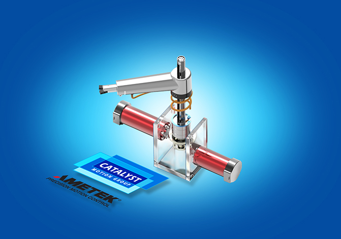
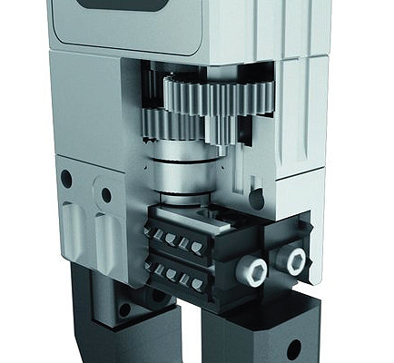
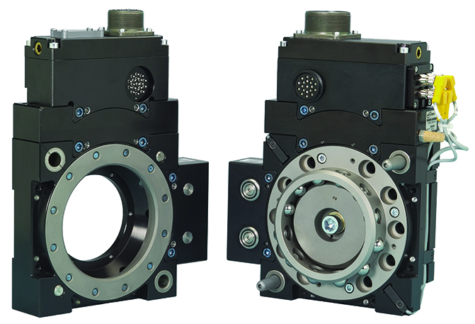
Electromechanical grippers use ballscrews, belts, or racks and pinions to connect to the jaw or finger that is touching or gripping the part. They are driven by a motor for tasks like loading and unloading machines to assembly lines. They can grip small parts, like an IC chip, up to very large pieces, such as a railroad wheel assembly greater than 3,000 lb. They are also ideal when tight precision is needed or when lifting larger, heavier items. Normally electromechanical grippers are made of aluminum and steel components, but some designs can be manufactured from composites like carbon fiber and other plastics.

Some specifics on electromechanical grippers

electromechanical-gripper-2
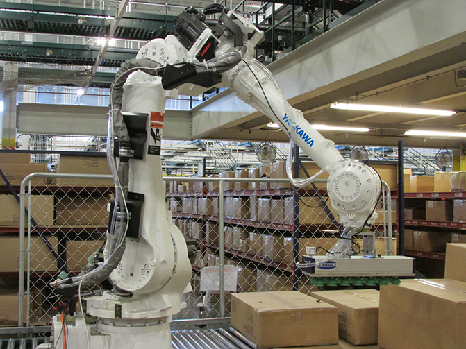
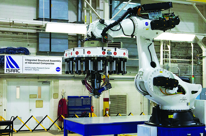
Electromechanical grippers are most common in pick-and-place robotics to put items on assembly lines, conveyor systems, or other automated systems. Fingered tooling, or jaws, are attached to the grippers to grip or hold the object.

They come in myriad styles and powered designs. Three common types are parallel, three-finger, and angled designs. The most common are parallel designs, with two fingers that close on a workpiece to grip it or open it out by creating pressure on the inside. Three-finger designs hold the workpiece in the center, and have three fingers offset by 120°. Finally, angled designs feature jaws that work at a variety of different angle openings (for example, 30°, 40°, and so on).

electromechanical-gripperIn addition, three choices of power are available, the most common being pneumatic grippers and the least common being hydraulic designs, with electromechanical designs in between.

Electromechanical grippers use ball screws, belts or racks and pinions to connect to the jaw or finger that is touching or gripping the part. They are driven by a motor for tasks like loading and unloading machines to assembly lines. They can grip small parts like an IC chip up to very large pieces such as a railroad wheel assembly greater than 3000 lb. They are also ideal when tight precision is needed or when lifting larger, heavier items.

Normally electromechanical grippers are made of aluminum and steel components, but some designs can be manufactured of composites like carbon fiber and other plastics.

When selecting a gripper, consider the following:

• Part weight and size to be lifted
• Part material
• Clearance issues around the part that could interfere with the gripping part,
• The environment in which the gripper will be used — corrosive, food or beverage, and so on
• The motion path of the robot or linear device that is moving the gripper
• The power supply that will be available

NASA's Langley Research Center is in the process of setting up this advanced composite research capability that engineers are calling ISAAC for Integrated Structural Assembly of Advanced Composites. The goal of the ACP is to reduce the time for development, verification, and regulatory acceptance of new composite materials and design methods. NASA will meet this objective through the development and use of high fidelity and rigorous computational methods, new test protocols, and new inspection techniques.
NASA’s Langley Research Center is in the process of setting up this advanced composite research capability that engineers are calling ISAAC for Integrated Structural Assembly of Advanced Composites. The goal of the ACP is to reduce the time for development, verification, and regulatory acceptance of new composite materials and design methods. NASA will meet this objective through the development and use of high fidelity and rigorous computational methods, new test protocols, and new inspection techniques.

06-INSET-ATI-Tool-Changer-Robotic-Carbon-Fiber-System

Filed Under: FAQs + basics Tagged With: phd, SCHUNK

Reader Interactions

Leave a Reply

You must be logged in to post a comment.

Primary Sidebar

POWER TRANSMISSION REFERENCE GUIDE

DESIGN GUIDE LIBRARY

“motion
Subscribe Today

RSS Featured White Papers

  • Specifying electric rodless actuators: Ten tips for maximizing actuator life and system performance
  • The truth about actuator life: Screw drive survival
  • Top Ten Tips: How to specify electric rod-style actuators for optimal performance, reliability and efficiency

Footer

Motion Control Tips

DESIGN WORLD NETWORK

Design World Online
The Robot Report
Coupling Tips
Linear Motion Tips
Bearing Tips
Fastener Engineering.

MOTION CONTROL TIPS

Subscribe to our newsletter
Advertise with us
Contact us
About us
Follow us on TwitterAdd us on FacebookAdd us on LinkedInAdd us on YouTubeAdd us on Instagram

Copyright © 2022 · WTWH Media LLC and its licensors. All rights reserved.
The material on this site may not be reproduced, distributed, transmitted, cached or otherwise used, except with the prior written permission of WTWH Media.

Privacy Policy | RSS