
 Switched-reluctance motors are stepmotors that accept power to their stators (instead of their rotors) to use output mechanical force through the use of reluctance. This is magnetomotive force to magnetic flux.
Switched-reluctance motors use drives that differ from those that pair with other stepper motors. That’s because switched-reluctance motors have nonlinear magnetic behavior … but output high speeds and reliable operation when driven correctly.
 One difference is that drives for switched-reluctance motors must compensate for torque ripple. Traditional setups also need position feedback and sensors. Here, sensors ultimately make the whole design more costly … so some newer controls run algorithms for driving switched-reluctance motors without sensors.
Switched-reluctance drive basics
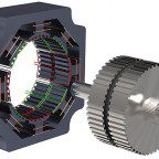
A typical switched-reluctance setup includes four components — the motor, a power converter, a logic circuit, and sensors. Power converters for switched-reluctance motors require only one switch in series per phase windings because the torque is independent of current polarity. Each phase is independent, so the failure of one does not bring the whole motor down. There are a few types of converters:

Asymmetric bridge converters involve turning on two switches per phase. If the current gets too high, these switches are turned off.
This configuration stores energy in the motor’s phase windings to keep current flowing in the same direction until it depletes.
(n+1) switches and diodes are more efficient than asymmetric bridge converters.
This is because this configuration allows the power devices to share switch operation. (n+1) does have restricted control when phases overlap, however.

Bifilar drives contain bifilar windings. Bifilar refers to two wires wound around a common core.
Inserting these windings allows the circuit to restore magnetic energy. The voltage in the switches can be much higher than that of the voltage source. However, bifilar windings are complex.
A C-dump converter also recovers energy. It contains a capacitor the can resend stored magnetic energy back to the DC source. This setup uses a minimal amount of power switches which allows independent phase control.
However, there is a drawback of limited commutation because of the voltage difference between the capacitor and the supply. Any energy circulating between the capacitor and the connection causes additional losses in the switched-reluctance motor itself.

Sensors are another component of switched-reluctance motor drives. These can come as a variety of encoders.
For a discussion of various encoder types, read:
FAQ: What is the difference between absolute and incremental encoders?
FAQ: How to use incremental encoders with stepper motors?
FAQ: Why are so many designers replacing resolvers with encoders?
When combining sensors and drive circuits, various control methods are possible. Carefully controlling the current makes a smooth torque-speed curve. As new control methods continue to proliferate, even better control characteristics are becoming possible. On this topic, read FAQ: How could drives soon make switched-reluctance motors more common?
For more information on switched-reluctance motors …
PDF download — University of Technology, Sydney: Switched Reluctance Motor
PDF download — Texas Instruments: Switched Reluctance Motor Control – Basic Operation and Example Using the TMS320F240

Leave a Reply
You must be logged in to post a comment.