• Skip to primary navigation
  • Skip to main content
  • Skip to primary sidebar
  • Skip to footer

Motion Control Tips

Automation • Motion Control • Power Transmission

  • News
    • Industry News
    • Editor Blogs
    • Video
  • Controls
    • HMIs
    • PC-Based Controllers
    • PLCs + PACs
    • Stand-Alone Controllers
    • Software
  • Drives
    • Servo Drives
    • Stepper Drives
  • Encoders
    • Absolute Encoders
    • Incremental Encoders
    • Rotary Encoders
  • Mechanical
    • Bearings
    • Brakes + Clutches
    • Belt + chain
    • Couplings
    • Gears + Gearing
    • Lubrication
    • Shock + Vibration Mitigation
    • Springs + Rings + Seals
  • Linear
    • Actuators
    • Linear Motors
    • Linear Encoders
  • Motors
    • AC Motors
    • DC Motors
    • Brushless Motors
    • Gearmotors
    • Piezo Motors
    • Servo Motors
    • Stepper Motors
  • Systems
    • Conveyors + linear transport systems
    • Gantries + Stages
    • Rotary Tables
    • Grippers + End Effectors
    • Robotics
  • Networks
    • Connections + Sliprings
    • Fieldbuses
    • I/O
    • Sensors + Vision
  • FAQs
    • Motion Casebook
    • Motion Selection Guides
  • Suppliers
You are here: Home / FAQs + basics / FAQ: What are hybrid stepper motors?

FAQ: What are hybrid stepper motors?

June 8, 2015 By Zak Khan Leave a Comment

Hybrid stepper motors combine aspects of both permanent magnet (PM) and variable reluctance (VR) stepper motors. Like PM motors, they contain a permanent magnet in the rotor teeth. Two sets of teeth called cups ring the rotor. One ring is all south poles, and the other ring is all north poles.

Like VR motors, hybrid stepper motors have stator poles. Note that stator poles in hybrid motors are sometimes called teeth. (For more information, read FAQ: What is pole count and why does it matter?) More after the jump.

Shown here are the rotor and stator of a hybrid stepper motor. Two soft iron cups sport teeth to guide the flux from a permanent magnet to the rotor-stator air gap.

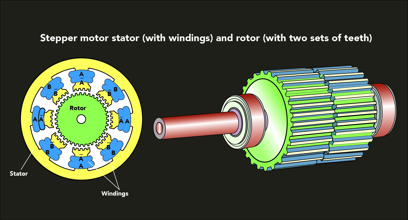
To illustrate how these motors work, consider a 1.8° hybrid stepper. The teeth of one ring are offset from those on the other ring by 3.6°. The stator poles are offset by 90° and these are opposite polarity, so that every 180° the stator poles are in identical polarity. The rotor poles exist in sets of four, with two being north poles and two being south poles. The rotor poles align alternately with the rotor’s teeth and cups, so that one set of rotor poles attracts fully while the other attracts and repels ¾, ½ or ¼ of a tooth. If there are 50 teeth, the pitch angle is 7.2° … so at the next step, the motor rotates to the next closest step, which is 7.2° × ¼ = 1.8°.

When the current changes, the rotor can turn a very small amount—an improvement over basic PM motors and VR motors. Newer control techniques such as half-stepping and microstepping let designers get even finer movements of rotation, which make for more exact output than that from VR stepper motors (which can’t usually be microstepped). Hybrid stepper motors also have higher torque-to-size ratios and higher output speeds than other stepper-motor types. They are also quieter than VR stepper motors.


One caveat is that hybrid stepper motors are more expensive than other step motors. So, designers should weigh the higher cost against the advantages of quiet operation, smaller steps, and torque output before making a final step-motor selection.

For more information, read:
Permanent Magnet in Motors—Construction and Operating Theory
Motion Control Hybrid Stepper Motors page

You may also like:


  • PC-based control on industrial sheet-metal presses — a Casebook example

  • Bodine’s SCR-rated PMDC gearmotors — for hybrid applications
  • Vehicles with long-range LiDAR (employing frameless motors from Lin Engineering) can anticipate the need to brake earlier
    Frameless brushless dc motors in hybrid solid-state LIDAR Applications
  • wound field motors
    What are wound field motors and where are they applied?
  • servo motor
    Hybrid servos vs. standard servos: How do they stack up?

Filed Under: FAQs + basics, Motors, Stepper Motors

Reader Interactions

Leave a Reply Cancel reply

You must be logged in to post a comment.

Primary Sidebar

MOTION DESIGN GUIDES

“motion

“motion

“motion

“motion

“motion

“motion

“motion

“motion

POWER TRANSMISSION REFERENCE GUIDE

RSS Linear Motion Tips

Subscribe Today

RSS Featured White Papers

  • Identifying Best-Value Linear Motion Technologies
  • Learn how to reduce noise and distortion in encoders’ signals
  • Helical Planetary Gearboxes: Understanding The Tradeoffs
Tweets from https://twitter.com/Motion_Control/lists/motion-control-tweets

Footer

Motion Control Tips

DESIGN WORLD NETWORK

Design World Online
The Robot Report
Coupling Tips
Linear Motion Tips
Bearing Tips
Fastener Engineering

MOTION CONTROL TIPS

Subscribe to our newsletter
Advertise with us
Contact us
About us
Follow us on TwitterAdd us on FacebookAdd us on LinkedInAdd us on YouTubeAdd us on Instagram

Copyright © 2021 · WTWH Media LLC and its licensors. All rights reserved.
The material on this site may not be reproduced, distributed, transmitted, cached or otherwise used, except with the prior written permission of WTWH Media.

Privacy Policy | RSS