• Skip to primary navigation
  • Skip to main content
  • Skip to primary sidebar
  • Skip to footer

Motion Control Tips

Automation • Motion Control • Power Transmission

  • News
    • Industry News
    • Editor Blogs
    • Video
  • Controls
    • HMIs
    • PC-Based Controllers
    • PLCs + PACs
    • Stand-Alone Controllers
    • Software
  • Drives
    • Servo Drives
    • Stepper Drives
  • Encoders
    • Absolute Encoders
    • Incremental Encoders
    • Rotary Encoders
  • Mechanical
    • Bearings
    • Brakes + Clutches
    • Belt + chain
    • Couplings
    • Gears + Gearing
    • Lubrication
    • Shock + Vibration Mitigation
    • Springs + Rings + Seals
  • Linear
    • Actuators
    • Linear Motors
    • Linear Encoders
  • Motors
    • AC Motors
    • DC Motors
    • Brushless Motors
    • Gearmotors
    • Piezo Motors
    • Servo Motors
    • Stepper Motors
  • Systems
    • Conveyors + linear transport systems
    • Gantries + Stages
    • Rotary Tables
    • Grippers + End Effectors
    • Robotics
  • Networks
    • Connections + Sliprings
    • Fieldbuses
    • I/O
    • Sensors + Vision
  • FAQs
    • Motion Casebook
    • Motion Selection Guides
  • Suppliers
You are here: Home / FAQs + basics / FAQ: What are lead-lag stepper motor controls?

FAQ: What are lead-lag stepper motor controls?

July 24, 2015 By Zak Khan Leave a Comment

Lead-lag controls or compensators are pieces of programming in control systems that improve frequency response.

  • A lead control can increase a system’s stability or its response speed.
  • A lag control can reduce steady-state errors.

Different combinations change output in different ways.

A note on terminology: The terms controller and compensator have several different meanings. Some engineers and manufacturers use these terms interchangeably. Others differentiate between the two. Some designers use controller to only refer to physical hardware — and compensator to refer to the algorithms that the hardware runs. Still others use compensator to refer only to filters that compensate for potential control-loop deficiencies. These add the exact number of variables present back to the system (while in contrast, controllers add a different number of variables back).

Lead-lag Bode phase diagram
This is a simplified Bode phase diagram of the effects of lead-lag controls.

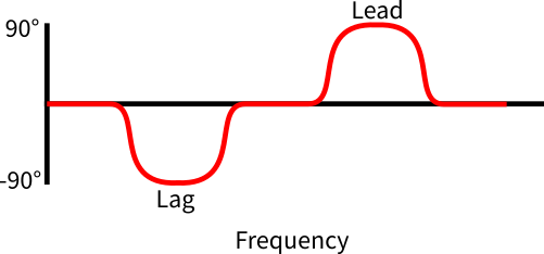
Regardless of terminology differences, design engineers use controllers and compensators to improve frequency response. Lags and leads apply to phases. Lead is a way to shift the phase angle of the output curve before the input curve. Lag is a way to shift the phase angle of the output curve after the input curve. So, lead-lag controllers do both. Tip: when selecting lead-lag controls, determine what level of closed-loop performance the machine needs. An appropriate lead-lag controller (along with the other components in the system) should satisfy design specifications.

Lead-lag controllers require a closed-loop operation. They use system feedback as part of their algorithms. This adds system complexity, but (as mentioned) improves overall system frequency response. This is especially useful for addressing noise, vibration and resonant frequency problems. Read FAQ: Aren’t heat and noise common stepper motor problems? for more information.

When determining if a lead-lag controller is right for a given system, ask:

  • Is a closed-loop system appropriate for the design, or is it overkill? Here, remember that better controls come at slightly higher cost.
  • Are their machine problems such as vibration that a lead-lag controller can fix? If there are such problems, determine if a lead-lag controller is the best solution.
  • Does the machine need off-the-shelf functionality? Lead-lag controllers suit specific systems, so require custom setup.

For more information on lead-lag, read:

Matlab Control Tutorials, Extras: Designing Lead and Lag Compensators

Filed Under: Actuators, FAQs + basics, Linear Motion, Motors, Stepper Motors

Reader Interactions

Leave a Reply

You must be logged in to post a comment.

Primary Sidebar

POWER TRANSMISSION REFERENCE GUIDE

DESIGN GUIDE LIBRARY

“motion
Subscribe Today

RSS Featured White Papers

  • Specifying electric rodless actuators: Ten tips for maximizing actuator life and system performance
  • The truth about actuator life: Screw drive survival
  • Top Ten Tips: How to specify electric rod-style actuators for optimal performance, reliability and efficiency

Footer

Motion Control Tips

DESIGN WORLD NETWORK

Design World Online
The Robot Report
Coupling Tips
Linear Motion Tips
Bearing Tips
Fastener Engineering.

MOTION CONTROL TIPS

Subscribe to our newsletter
Advertise with us
Contact us
About us
Follow us on TwitterAdd us on FacebookAdd us on LinkedInAdd us on YouTubeAdd us on Instagram

Copyright © 2022 · WTWH Media LLC and its licensors. All rights reserved.
The material on this site may not be reproduced, distributed, transmitted, cached or otherwise used, except with the prior written permission of WTWH Media.

Privacy Policy | RSS