
A stepper drive is the driver circuit that controls how the stepper motor operates. Stepper drives work by sending current through various phases in pulses to the stepper motor. There are four types: wave drives (also called one-phase-on drives), two-phase on, one-two phase-on drives and microstepping drives.
Wave or one-phase-on drives work with only one phase turned on at a time. Consider the illustration below. When the drive energizes pole A (a south pole) shown in green, it attracts the north pole of the rotor. Then when the drive energizes B and switches A off, the rotor rotates 90° and this continues as the drive energizes each pole one at a time.
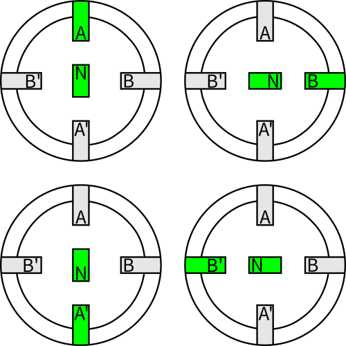
Engineers rarely use wave driving: it is inefficient and provides little torque, because only one phase of the motor engages at a time.
Two-phase-on driving has its name because two phases are on at a time. If the drive energizes both A and B poles as south poles (shown in green), then the rotor’s north pole attracts to both equally and aligns in the middle of the two. As the energizing sequence continues on like this, the rotor continuously ends up aligning in-between two poles.
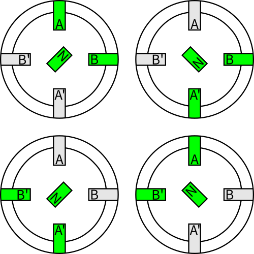
Two-phase-on driving gets no finer resolution than one-phase on, but it does produce more torque.
One-two phase-on driving has its name for the way the drive energizes either 1 or 2 phases at any specific time. In this driving method, also known as half-stepping, the drive energizes pole A (shown in green) … then energizes poles A and B … then energizes pole B … and so forth.
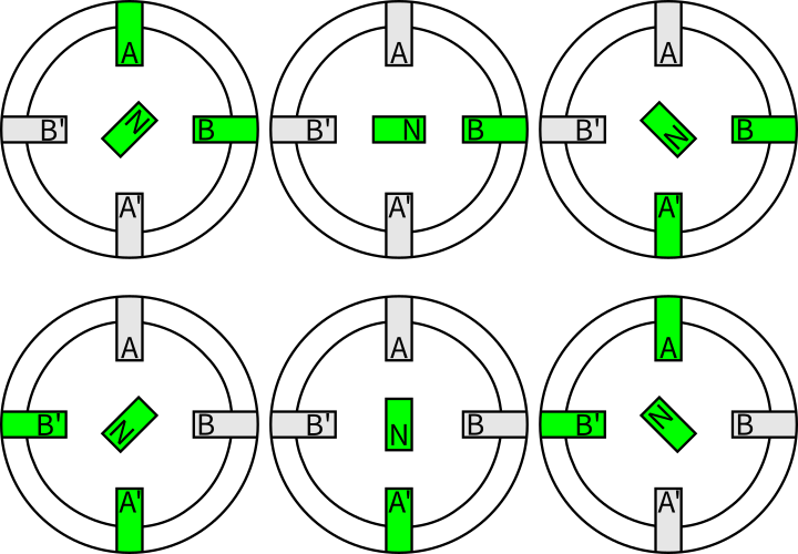
One-two phase-on driving delivers finer motion resolutions. When two phases are on, the motor produces more torque. One caveat here: torque ripple is a concern because it may cause resonance and vibration.
Related to one-two phase-on driving is microstepping.
Microstepping delivers very fine motion resolutions. Here, the drive uses current regulation to prevent torque oscillations. With this technique, engineers can use stepper motors in more applications.
In sort, a drive that is microstepping increases and decreases current along a sine wave, so no pole is fully on or off. Here is a sample microstepping sine-wave current:

Note the subtle jagged contour of the sine-wave current. While microstepping doesn’t necessarily improve accuracy, it does get higher resolution than other driving modes—which is particularly helpful for applications in which the motor goes through no-load situations. During operation, motors can miss steps. However, microstepping spreads energy out instead of delivering it to the motor all at once, which can cause ringing and overshoot.
For all of these forms of driving, the motors can have different windings. Unipolar motors only accept positive voltage. Unipolar requires an extra wire in the middle of every coil to let current flow from one end to the other. Bipolar stepper motors use both positive and negative voltage. Bipolar stepper motors have more torque because they produce a stronger magnetic field, but their construction also requires more wire.
For more information:
Oriental Motor’s website on stepper motors
University of Texas at Austin: Archived STMicroelectronics PDF
Leave a Reply
You must be logged in to post a comment.