• Skip to primary navigation
  • Skip to main content
  • Skip to primary sidebar
  • Skip to footer

Motion Control Tips

Automation • Motion Control • Power Transmission

  • News
    • Industry News
    • Editor Blogs
    • Video
  • Controls
    • HMIs
    • PC-Based Controllers
    • PLCs + PACs
    • Stand-Alone Controllers
    • Software
  • Drives
    • Servo Drives
    • Stepper Drives
  • Encoders
    • Absolute Encoders
    • Incremental Encoders
    • Rotary Encoders
  • Mechanical
    • Bearings
    • Brakes + Clutches
    • Belt + chain
    • Couplings
    • Gears + Gearing
    • Lubrication
    • Shock + Vibration Mitigation
    • Springs + Rings + Seals
  • Linear
    • Actuators
    • Linear Motors
    • Linear Encoders
  • Motors
    • AC Motors
    • DC Motors
    • Brushless Motors
    • Gearmotors
    • Piezo Motors
    • Servo Motors
    • Stepper Motors
  • Systems
    • Conveyors + linear transport systems
    • Gantries + Stages
    • Rotary Tables
    • Grippers + End Effectors
    • Robotics
  • Networks
    • Connections + Sliprings
    • Fieldbuses
    • I/O
    • Sensors + Vision
  • FAQs
    • Motion Casebook
    • Motion Selection Guides
  • Suppliers
You are here: Home / FAQs + basics / How to select gear ratio for a gear reducer?

How to select gear ratio for a gear reducer?

November 9, 2018 By Miles Budimir Leave a Comment

This is the first of a multi-part series on gear reducers. In this first part we look at selecting the proper gear ratio for a gear reducer.

The information here is supplied by Bodine Electric Company.

Gear reducers are an essential part of mechanical power transmission systems, being used for speed and torque conversion. Selecting the right one for an application is a fairly straightforward process. The first step in selecting a gear reducer is to know the required torque and speed as well as the most suitable type of motor to use. Then, it can be determined if a gear reducer is needed in the particular case. If so, then the next step is to select the proper type and ratio.

gear
A cutaway of a gear motor showing the internal worm gearing. (Image via Bodine Electric Company)

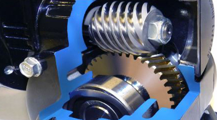
So what does a gear reducer do? The most common benefits are that they can reduce speed, multiply torque, and solve inertia mismatching issues. For instance, to take speed reduction, the amount needed will depend on the type of motor used. That’s because some motors can operate at low speeds (less than 1,000 rpm, for instance) without the need for a gear reducer, while others cannot.

For speed reduction the gear ratio is calculated using the equation:

G = NMOTOR / NLOAD

where G is the gear ratio, and N is the angular velocity of the motor and the load.

The way gear reducers work is that they essentially multiply the output torque of the motor. So for instance, a small motor with a gear reducer may be less expensive and smaller than a larger motor without a gear reducer producing an equal amount of torque.

To calculate the required gear ratio when torque multiplication is needed, use the equation:

G = TLOAD / [ TMOTOR x eGEARS ]

where G is the gear ratio, T is torque and e is efficiency.

Another function of gear reducers is to reduce the reflected load inertia to the motor by a factor of the square of the gear ratio. For most motion applications but especially high performance ones, the ideal condition is for the reflected load inertia to equal the motor inertia.

To calculate the gear ratio when inertia matching is the main concern, take the square root of the ratio of the load inertia to the motor inertia as in the equation:

G= sqroot [ JLOAD / JMOTOR ]

where G is the gear ratio and J is the inertia of the motor and load.

In part 2, we’ll look at the different types of gear reducers and how to select the best one.


You may also like:


  • How does a fixed-ratio traction drive work — and potentially…
  • inching drive
    What is an inching drive?
  • gearmotors
    How to design gearmotors for extreme ambient conditions
  • gearbox selection
    Three gearbox selection tools available online
  • cycloidal reducer
    Wave and cycloidal gearing explained: Strain-wave, planocentric, cycloidal, planetary, and…

Filed Under: FAQs + basics

Reader Interactions

Leave a Reply

You must be logged in to post a comment.

Primary Sidebar

POWER TRANSMISSION REFERENCE GUIDE

DESIGN GUIDE LIBRARY

“motion
Subscribe Today

RSS Featured White Papers

  • Specifying electric rodless actuators: Ten tips for maximizing actuator life and system performance
  • The truth about actuator life: Screw drive survival
  • Top Ten Tips: How to specify electric rod-style actuators for optimal performance, reliability and efficiency

Footer

Motion Control Tips

DESIGN WORLD NETWORK

Design World Online
The Robot Report
Coupling Tips
Linear Motion Tips
Bearing Tips
Fastener Engineering.

MOTION CONTROL TIPS

Subscribe to our newsletter
Advertise with us
Contact us
About us
Follow us on TwitterAdd us on FacebookAdd us on LinkedInAdd us on YouTubeAdd us on Instagram

Copyright © 2022 · WTWH Media LLC and its licensors. All rights reserved.
The material on this site may not be reproduced, distributed, transmitted, cached or otherwise used, except with the prior written permission of WTWH Media.

Privacy Policy | RSS