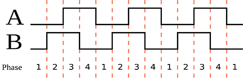
Incremental encoders, like absolute encoders, are used to track motion as well as to determine speed and position. Incremental encoders generally supply square-wave signals in two channels, A and B, which are offset by 90 degrees, or out-of-phase by 90 degrees. This helps in determining the direction of rotation.
The output signals of an incremental encoder only have information on relative position not absolute position like an absolute encoder. In order for the encoder to provide any useful position information, the position of the encoder has to be referenced in some way, traditionally using an index pulse. So the incremental encoder sends incremental position changes to electronic circuits that perform the counting function.
On start-up, the encoder will home in on a known, fixed position, which serves as a fixed reference point going forward. This fixed position can be either fixed by a magnetic point or strip of mechanically by a limit switch.
One traditional limitation of an incremental encoder is that the number of pulses counted is stored in an external or buffer counter which can be lost if there is an interruption of power. For instance, if a machine with an encoder is turned off, the encoder will not know its position when switched on again. The encoder has to perform a homing routing in order to know its exact position, forcing the motor to move until a home limit switch is activated. Then, a counter or buffer will be zeroed and the system will determine where it is relative to fixed positional points. One way around this issue of loss of power is to use a battery backup system. Such a solution ensures that the memory is backed up and can store the count information and provide an absolute count once power is restored.
Standard Quadrature A and B signals used in incremental encoders are shown in the graph above. Electronic circuitry interprets the raw data to determine position as well as the direction of rotation.


Leave a Reply
You must be logged in to post a comment.