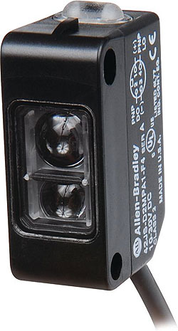
Sensors for motion applications include position sensors, speed and proximity sensors.
Linear position sensors are used to determine the position of a mechanical component in a broad range of applications. Linear position sensors use an inductive oscillating circuit coupling positioned between the actuator and sensor. Emitter and receiver coil systems are precisely arranged on a printed circuit board. A high frequency AC field activates the coil system and produces an inductive RLC circuit with the positioning element, also referred to as the resonator. As a result, the resonator is inductively coupled with the receiver coils. Different voltages are induced into the coils, depending on the position of the resonator, and these voltages serve as a measure for the sensor signal.
Traditional sensor types used in linear position applications also include magnetostrictive sensors, which measure the space from a position magnet and the head of a sensing rod through the use of magnetic signals, as well as potentiometer sensors that generate a resistance output in proportion to the position of the mechanical component. Newer linear position sensors provide an accurate and robust alternative to magnetostrictive and potentiometer devices for applications including metal processing machines, rolling mills, or injection molding machines.
Inductive proximity sensors remain the first choice for detecting metallic targets at short ranges. However, many other types of targets and ranges require a different kind of sensor. Some of the most widely used types include capacitive, photoelectric, and ultrasonic sensors.
Compared to capacitive sensors, photoelectric sensors operate on the principle of transmitting and receiving light. Three basic modes of operation for photoelectric sensors include diffuse, retro-reflective, and through-beam. All three offer reliable, long-range target detection.
Through-beam sensors consist of a separate emitter and receiver housing. Passing the target between them blocks light transmission to the receiver and changes the state of the output. Retro-reflective sensors operate in a similar way, except both the emitter and receiver are in the same housing. The light is blocked between the sensor and a reflector, which has been mounted in space—typically to simplify wiring or to fit in a space where a second housing will not.
Diffuse sensing relies on the target to reflect light back to the sensor where the emitter and receiver are both located. By using different combinations of processing circuits, emitters, receivers, and lenses, specialty types of diffuse sensors are available including background suppression, full-color detection, color-mark inspection, luminescent-mark sensing, and distance measurement.
Photoelectric sensors are ideal for a number of measurement and detection applications, such as counting and orienting parts, detecting product defects, and verifying sizes at extremely long sensing ranges. However, some drawbacks include target-surface reflectivity, target color, and target opacity. Photoelectric sensors are superior for many precision tasks where their unique operating modes gives them a clear advantage, but they are also the most susceptible to changes in material color, opacity, or surface texture.
When choosing a sensor, consider its flexibility, such as a sensor with features that adapt to changing product and packaging media is key. Or for example, consider selecting a sensor with universal outputs. A sensor that has both NPN and PNP outputs reduces selection and stocking requirements. If a customer requires a different controller that accepts only sinking NPN transistor outputs, then using a sensor with multiple output types saves time. Some sensors have NPN and PNP outputs, as well as normally open and normally closed modes. A sensor that automatically selects the output based on the connected load can also be helpful.
Always select a sensor that can be used under and over its specification limits. A proximity sensor used at 75% of its range instead of 95% of its range ensures that future machine changes and tolerances will be much less likely to affect it. It is better to select a flexible component up-front than discover its limitations later.
Background suppression, a photoelectric sensing mode, is uniquely equipped to eradicate changeover time because it detects various materials—regardless of color, print, and reflectivity—at nearly identical distances. No adjustment or realignment is necessary. Sensors equipped with background suppression also ignore the shiniest background machine panels, and they do not require reflectors.
Program sensor settings for automatic and speedy adjustments rather than configuring individual sensor settings. User-friendly, simple adjustments (e.g. potentiometer, push-button, or other methods) can minimize sensor setup time.
One way to reduce programming time is for the controller, rather than a technician, to teach the sensor. PLCs can send signals to many sensors to trigger them to learn new targets. Contrast sensors for registration mark detection are one example. The sensor will automatically re-learn the eye-marks on a roll of web-stock every time a new roll is loaded.


Leave a Reply
You must be logged in to post a comment.