by Christian Fritz, Sr. Product Manager, Advanced Machine Control, National Instruments, Austin, Tx.
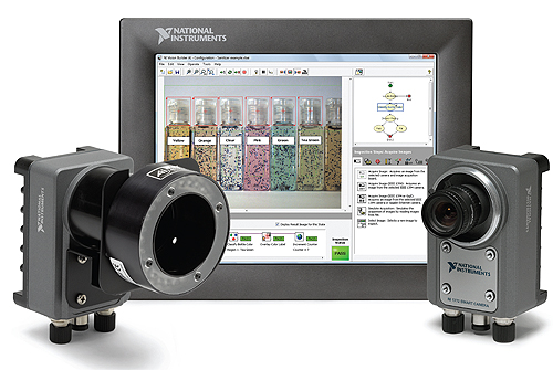
For decades the adoption of machine vision technology has been a growing trend in the automation industry. Applications like quality inspection, robot guidance, pick-and-place operation and part sorting experienced a quantum leap in performance through the adoption of image acquisition and processing.
The connectivity to motion control systems or robot controllers through industrial buses and protocols enables engineers to integrate machine vision into existing processes and make decisions based on the results of image analysis without the need to completely redesign their controller architecture. For many applications a basic open-loop implementation is sufficient. In this case, the sequence starts with the vision subsystem capturing the image of an object. After processing the image, the vision subsystem determines the coordinates of the part in pixels and then converts the pixel coordinates to real-world coordinates. These coordinates are then provided to the motion subsystem which determines the trajectory for a coordinated multi-axis move.
Basics
In a basic vision-guided motion system, the vision subsystem provides guidance to the motion system only at the beginning of a move and possibly verifies that the move was correctly executed at the end of the operation, but there is no feedback during the move. This lack of feedback makes the move prone to errors in the pixel-to-distance conversion and the accuracy of the move is entirely dependent on the motion subsystem. This drawback becomes prominent in high accuracy applications with movement in the sub-millimeter range. To eliminate this shortcoming, the vision subsystem needs to provide continuous feedback to the motion subsystem during the move.
This advanced type of vision guidance is called visual servo control. In visual servo control, the vision system provides feedback in the form of the position set points for the position loop (dynamic look and move) or the actual position feedback (direct servo). The dynamic look and move approach is becoming increasingly common in industrial applications especially for robot applications. The ever increasing performance of vision systems allows for closed-loop feedback systems where the vision system is connected to the motion (or robot) controller via specific I/O lines or more commonly industrial protocols like EtherCAT. The results are smarter robots that provide increased accuracy and which are relatively insensitive to calibration errors or non-linearities. But, similar to any other closed-loop system, the additional feedback loop requires tuning and allows the possibility of instability.
Direct servo applications use visual input as the only feedback for the motor position or velocity control. In order to be useful and applicable, this approach requires a way to extract position or velocity information from a series of images acquired at very high speeds. Any solution is therefore application specific and any given implementation is typically not broadly applicable.
Semiconductor Industry Example
One application example comes from the semiconductor industry. In semiconductor manufacturing, the push for greater efficiency and higher yield of silicon semiconductor material is ongoing. As circuit features shrink in size and global price competition intensifies, wafer processes push the physical and operational limits of equipment manufacturers. One result is increasingly narrow tolerances for incoming wafer physical and electrical parameters in delicate process steps, such as mask and etch. Extremely accurate positioning and consistent movement on top of the semiconductor surface are important in many different steps of wafer processing.
The recurring pattern on the surface of wafers is one obvious way to obtain position or velocity information. A camera that moves relative to the repetitive pattern captures images at high speeds. These images are analyzed to generate the equivalent of an encoder signal. Then, the image processing algorithms extract a single element of the pattern and determine its location. Based on this information, the motion trajectory generator algorithm creates a motion profile that meets the application requirements, typically either a profile that minimizes the position error or a constant velocity profile.
To effectively control the motor, the position set points or feedback needs to be generated at the rate of tens of milliseconds to sub-milliseconds which requires the vision system to acquire and process images at extremely high frame rates. With these increased requirements with regards to timing and synchronization, the realization of visual servo control has a significant impact on the control architecture and typically eliminates the possibility to leverage standard off-the-shelf motion and vision systems and industrial communication. In a search for alternatives, machine builders are looking at high-performance embedded systems to integrate the motion and vision tasks on a single hardware platform. Pushed out of their comfort zone, many of them approach automation suppliers to deliver more flexible hardware solutions and software tools.
Historically, embedded systems have featured a single central processing unit (CPU), so system designers have mainly relied on CPU clock speed improvements and the shift to multi-core computing to achieve the processing throughput required for consolidating automation tasks. But modern embedded processors also feature a much deeper instruction pipe length and predictive branch mechanisms to further increase the processing performance. As a result, modern processors might need hundreds of clock cycles to service an interrupt request that has a significant impact on system determinism. While this is acceptable for many applications, low-level control loops for high-speed, high-accuracy motor control can’t handle increased jitter and latency. In addition, streaming oriented processing tasks like image processing require high memory throughput that is still a bottleneck in many embedded processor systems.
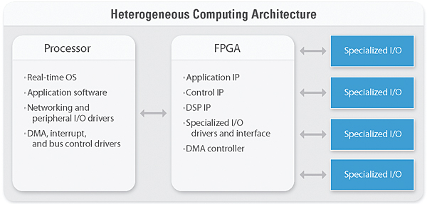
One way to achieve determinism at extremely high computational levels and gain flexibility in regards to data streaming is to replace processing and data-intensive firmware algorithms with custom hardware and leverage programmable logic. In recent years, the industry heavily adopted Field Programmable Gate Arrays (FPGAs) for a broad range of applications. Automation suppliers leverage FPGAs because they can quickly adapt products to evolving standards and processing requirements, to keep pace with market requirements, and to add features and functions even after the product release. To get the best from both worlds, system designers are migrating to computing architectures that feature multiple distinct processing elements, to provide an optimal balance between throughput, latency, flexibility, cost, and other factors. Heterogeneous computing architectures provide all of these advantages and enable the implementation of high-performance embedded systems for vision and motion integration.
To illustrate some of the benefits that heterogeneous computing architectures can provide, consider an architecture composed of a CPU, an FPGA, and I/O. FPGAs are ideally suited to handle parallel computations such as parallel control loops, signal or image processing operations on a large number of data channels. FPGAs are reprogrammable silicon chips. In contrast to processors, programming an FPGA rewires the chip itself to implement your functionality rather than run a software application. This low-level access to hardware allows the customization of motor control algorithms and the implementation of image processing on parallel hardware, which increases speed and reduces jitter and latency.
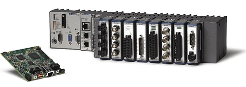
Off-the-shelf embedded system platforms based on heterogeneous architectures are available today and eliminate the need to design custom hardware. For instance, the National Instruments LabVIEW RIO architecture provides an off-the-shelf platform that’s available in a variety of form factors and performance levels from board-level single-board systems to industrially packaged systems with PXI connectivity. A broad range of I/O modules, including analog and digital measurements and industrial bus connectivity, helps engineers prototype and deploy visual servoing applications.
A key component of this architecture is NI’s graphical software development tool called LabVIEW, which makes it possible to program CPUs and FPGAs on heterogeneous hardware using a consistent graphical programming approach. In addition, LabVIEW abstracts system timing, I/O access, and inter-element communication based on knowledge of the underlying architecture and provides a wide range of IP libraries for automation tasks like motion control and machine vision.
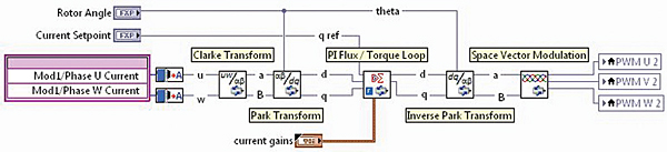
A motion control module called SoftMotion lets engineers program motion profiles with a high-level motion API and connect to standard motor drives. By moving the critical motor control IP to the FPGA and using special drive, drive interface, or generic I/O modules, machine builders can keep their high-level motion code and customize the lower-level IP or even implement their own algorithms.
LabVIEW lets engineers leverage existing IP on the real-time processor or the FPGA. The LabVIEW Vision Development Module and additional IP for image processing on FPGAs provide rich image processing functionality. Together these tools allow motion and vision experts to quickly design machine control applications ranging from simple look-and-move to cutting-edge visual servoing and deploy them to off-the-shelf embedded hardware.
National Instruments
www.ni.com
Leave a Reply
You must be logged in to post a comment.