Drives for stepper motors continue to advance beyond the basic L/R type drives.
A typical linear motion control system has several basic components, including motors, actuators, controllers and drives. The drive type plays an important role in the overall system. Here’s a look at the most basic drive configurations, including the latest advancements in chopper drives.
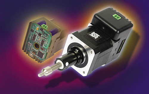
The IDEA programmable actuator from Haydon Kerk is an example of cutting-edge intelligent chopper drive technology. IDEA consists of an advanced microstepping chopper drive with an intelligent programmable controller mounted to the rear section of a hybrid stepper motor linear actuator in one fully integrated package.
Defining the L/R Type Drive
An L/R type drive is a voltage source drive, where the L refers to electrical inductance and R stands for electrical resistance. Inductance is an electrical parameter relating mainly to inductors that are coils of wire wrapped around a core material that can be metallic, non-metallic, solid, liquid, or even air. Typical inductors are transformers, chokes, and motor coils (including the windings in stepper motors and stepper motor linear actuators). A related parameter called inductive reactance in an electrical circuit impedes the flow of current relative to the voltage frequency. It can be thought of as a “dynamic resistance,” increasing and impeding more of the current flow as the frequency increases. An analogy for inductance in the mechanical field would be the principle of inertia.
Resistance also impedes the flow of current in an electrical circuit but is a constant value and is not affected by the frequency value of the voltage or current. The stepper motor coil resistance remains essentially the same from standstill through maximum step frequency with only minor fluctuations due to temperature. A mechanical equivalent of electrical resistance would be the friction in a system.
Stepper motor manufacturers offer a variety of coil voltage ratings. With an L/R type of drive, you set the output voltage of the drive (measured at the motor leads) equal to the voltage rating of the stepper motor. The voltage level of the drive power supply will be set slightly higher due to voltage drops across the power transistors. The ratio of inductance to resistance (L/R) determines the current flow through the windings at a given step rate (or frequency) in steps per second. L/R = 1 time constant, which is equal to approximately 63% of the final steady-state current. At standstill, the maximum current flow into the windings is determined by the coil resistance alone. The impedance effect due to inductance is zero when the frequency is zero. This is the condition where the motor has maximum torque (holding torque) due to maximum ampere-turns, defined by:
TH α N x I
Where:
TH = the holding torque
N = the number of turns in the motor coil
I = the electrical current
As the step rate increases, the coil inductive reactance (XL) also increases according to the formula:
XL = 2πfL
Where:
XL = the inductive reactance
f = the frequency (step rate)
L = the inductance of the motor coil
With a constant voltage source L/R type driver, the motor current decreases as the total impedance (XL + R) increases.
Because torque, both static and dynamic, depends on ampere-turns, the output performance of the stepper motor or stepper motor linear actuator drops off as the speed increases. Another factor affecting motor performance is the back-EMF (electro-motive force) produced by the rotor rotating in a magnetic field. Motors also behave as generators. High step rates may produce peak back-EMF levels approaching or exceeding the L/R drive output voltage level. One method used to partially compensate for these effects is to improve the inductance to resistance (L/R) ratio by adding external series resistors and increasing the power supply voltage. Some common configurations are the L/2R and the L/4R drivers. Because the respective voltage sources would have to be doubled or quadrupled, the efficiency drops significantly and much more of the power is wasted as heat in the external resistors.
Categories of L/R Drives: Unipolar and Bipolar
Unipolar drives have simple output configurations and are used infrequently due to the relatively low torque output and low efficiency. A unipolar drive contributes to a torque reduction of approximately 30% as compared to a bipolar drive at the same electrical power. In a unipolar drive, only half the phase winding is energized at one time, whereas in a bipolar drive, the entire phase winding is energized.
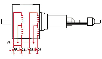
A unipolar drive configuration. Notice that the motor phase winding is center-tapped, thus allowing current to flow through only half the phase winding at a time.
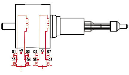
A bipolar drive configuration.
Bipolar drives have more complex output stages. Many of the new specialized integrated circuits have come down in cost, making bipolar drives more affordable. The output configuration is an “H-Bridge” which allows the reversal of the phase currents. Instead of the phase currents being switched on and off in just half of the windings like in a unipolar configuration, the currents flowing through the entire motor windings are reversed in bipolar drives. At equal electrical power into a given frame size stepper motor, the bipolar driver/motor configuration can produce greater static and dynamic torque than that of a unipolar driver/motor combination.
Chopper Drives
The term chopper refers to the method of rapidly switching a relatively high voltage to the windings on and off. This technique of switching the output voltage on and off controls the average current per phase.
There are several steps involved in selecting a chopper drive. First, choose a power supply that has a high output voltage relative to the voltage rating of the stepper motor to be driven. The high available voltage compensates for the increasing coil impedance due to rising inductive reactance as the motor speed increases. A power supply to motor coil voltage ratio of 8:1 or higher will provide the best performance at the higher motor speeds. Second, low-voltage steppers, with correspondingly lower inductance coils, are recommended. Linear type motor power supplies work well with these drives. Third, virtually all chopper-type drivers are a bipolar configuration, making use of the entire motor windings, which yields improved torque. Even unipolar stepper motors can be driven with these bipolar choppers as long as their rated coil voltage is not too high. Six-lead unipolar motors would be connected as a four-lead type by leaving the center-tap leads unconnected. With eight-lead steppers, you can connect the two coils of each phase in series (especially low-voltage coils) or in parallel. Because inductance changes as the square of the number of turns, putting two coils in series yields four times the inductance. Stepper motor performance improves at the higher speeds, as compared to an L/R type drive, due to the chopper drive’s method of monitoring and controlling motor current throughout the usable speed range.
To control the average current through the phase windings, this type of drive technology “chops” the high output voltage on and off. Most choppers use a fixed chopping frequency of approximately 20 kHz or higher. This helps keep system noise low, since the chopping frequency is above audible range. Based on this constant fixed chopping frequency, the average output current is controlled by varying the pulse width of these repetitive output pulses, a technique known as pulse width modulation (PWM).
The output current is monitored by comparing the voltage level across a small ohmic value series sense resistor with a set voltage that represents the rated motor current. During each cycle of the typical 20-kHz waveform, the voltage across the sense resistor begins to rise as the current increases through the motor winding. An electronic comparator continuously monitors this voltage level; when it equals the set reference voltage it turns off the output voltage until the start of the next 20-kHz cycle. The current in each motor winding builds and decays as the voltage source switches on and off during each cycle, yielding the proper average current per phase.
As the motor step rate, or speed, increases or decreases, so does the corresponding winding impedance and the chopper drive electronics help to compensate for this effect. At slow speeds (lower winding impedance) the on time of the voltage source is relatively short per cycle (small pulse width). At higher speeds (higher winding impedance) the on time is longer per cycle to allow the current to increase to the proper level (large pulse width); thus the term pulse width modulation.
Advances in Chopper Drives
Chopper drives are now selected for most new stepper motor linear actuator applications and there has been ongoing progress in this drive technology. For instance, the use of low on-resistance Field Effect Transistors (FETs) in the output power stage increases system efficiency and reduces power dissipation within the drive, which also reduces the required heatsink area and physical size of the drive package. Also, new power stage circuitry can provide the higher phase currents required from low-voltage, low-inductance motors, which can yield improved performance over a wider speed range. Enhanced phase current control increases motor performance such as automatically providing boosted current levels during acceleration and deceleration ramping, or shaping to reduce overall resonance of the system.
Other advances include multiple levels of microstepping (electronically splitting a full step into smaller increments) to increase motor resolution, reduce motor resonance, and lower the motor’s audible sound level during operation. Also, the integration of smart controllers, by use of on-board microprocessors, which allows for execution of real-time motion functions such as indexing with or without ramping, and creating complete interactive motion profile programs. These programs can be downloaded into non-volatile memory on the controller and then run independently and un-tethered from any host computer.
In the realm of I/O, interactive optically isolated inputs and outputs now allow the driver/controller to fully communicate with other devices and equipment in a motion control system. And smart controllers can accept encoder feedback, which can be used for motor positional verification or speed control.
Discuss this on the Engineering Exchange:

Haydon Kerk Motion Solutions
www.haydonkerk.com
::Design World::


Leave a Reply
You must be logged in to post a comment.