by Robert Gloeckner, Advanced Engineering Group, MICROMO
Innovative components help OEMs revolutionize designs. In fact, some original equipment can now benefit from zero-backlash actuators and integrated gearhead encoders. These give designers multiple options for demanding applications.
Performance, cost and size requirements for motion applications vary widely. In some cases, performance trumps all and the budget must simply tolerate the result. In others, the application demands performance but at reasonable price. As we’ll explore, if an application requires absolute accuracy, a gearhead encoder is an economical and compact solution. For applications that cannot tolerate any backlash, zero-backlash actuators remove it mechanically.
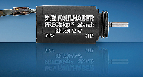
Consider a perfect motion system in which the controller sends a signal, and then the hardware delivers the load to the commanded position. In reality, error sources such as mechanical hysteresis and backlash compromise performance. With enough design time, effort and money, it’s possible to minimize these effects. However, motion is an enabling technology rather than an end in itself—which means OEMs generally aim to focus on their product’s unique value proposition, and not on matching gear teeth and damping vibration, for example.
Now, new technology simplifies performance optimization and makes it cheaper, too.
Preventing lost motion with tandem gearing
As mentioned, some zero-backlash actuators ensure stable performance for applications that cannot tolerate lost motion. To remove error caused by vibration, compliance and shock load, the gearhead encoder drives deviation to zero. That frees OEMs to focus on the development of innovative products of their own.
Even the best gearheads have small gaps between the teeth to let them mesh and maintain lubricant between contacting surfaces. The downside is that this space introduces a bit of lost motion called backlash. This shows up as positioning error, especially in precision applications with frequent reversals. Even for high-accuracy or precision gearheads, backlash still amounts to a few degrees of arc-min, and normal wear over the lifetime of the machine only worsens it. This is not a problem for a case packer or palletizer, but even that small amount of error is too much for applications such as robotics, optical positioning and gantries.
Over the years, motion vendors introduced designs to mitigate backlash using plastic spacers, split gears and springs to apply a preload that maintains contact between the gear teeth. But none are ideal, because they still exhibit a few arc minutes of error, and the preload needs adjusting for wear and environmental changes to maintain performance.
To address the problem, some zero-backlash actuators use an integrated assembly. These deliver fast and accurate positioning without backlash, which in turn delivers loads to commanded locations with minimal error. Compact and robust, the plug-and-play actuators also speed assembly and eliminate scrap.
Consider one specific setup with two motors. This design uses a gear flanked by two motor-driven pinions. One pinion positions the axis, and the other engages the opposite tooth flank and takes up backlash. During normal motion, the motors drive the load with combined torque. At the end of the move, the first pinion holds the position while the second pinion reverses to apply the counterforce. This effectively removes backlash mechanically. Such actuator gearheads perform equally well during acceleration, deceleration and reversals. They’re flexible in that the servo controller can adjust the preload to be softer or stiffer. Plus, it’s a scalable design.
In addition to two-motor setups, this design concept also implements with four or even six motors to increase torque while adding redundancy, especially in high-reliability applications.
Zero-backlash actuator options
Design engineers can choose from rotary and linear actuator configurations with myriad performance levels and form factors. For example, through-hole versions are useful for optical systems that operate in space-constrained applications. More specifically, through-hole zero-backlash actuators can position optical components while a laser beam shines through the aperture. The result is precise performance in a compact system. The aperture also lets users run cables through the center as a way to save space and reduce cable fatigue.

Such actuators also excel in gantries for pick-and-place operations, where backlash can cause binding (and compromise performance while making the system wear prematurely). Here, zero-backlash actuators ensure symmetrical motion so carriages can travel faster while handling heavier loads.
Just consider how the position of a solar cell on a satellite can mean the difference between a functioning device and a useless lump of space junk. In one real-world setup, the reliability and functionality of a zero-backlash actuator lets engineers optimize solar cell positioning. The actuator has also maintained solid performance, even under launch and orbital conditions.
Another approach: Driving error toward zero
In standard servo systems, an encoder mounted to the motor shaft monitors the number of rotations to estimate the position of the load. However, compliance, hysteresis and backlash all introduce error between predicted and actual load positions. This error can be as much as 2 to 3° in some cases. While that’s acceptable in many standard designs, demanding OEM applications can’t tolerate such error.
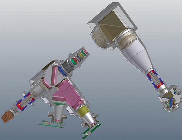
Precision OEM machines need an encoder mounted to the output shaft of the gearhead, not just the motor shaft. Such systems can operate on a dual control loop. They first close the loop around the motor encoder and then around the gearhead encoder. This configuration lets the controller measure the difference between predicted and actual location of the load (and compensate for the error). This process introduces a small amount of latency, but makes for highly accurate and precise output. It’s particularly effective for ultra-demanding applications such as micro-robotics.
3D printing and aerospace
Dual-control-loop techniques can be challenging, though. Space can be a factor. After all, adding an encoder to the gearhead won’t do much good if the assembly won’t fit. Mounting an encoder to a gearhead shaft involves mechanical, electrical and controls interfaces. That’s a non-trivial task that consumes time that would be better spent working on the actual product being designed.
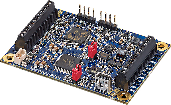
As one solution, some motion vendors offer magnetic gearhead encoders. These integrated packages are assembled in the factory and fine-tuned to optimize performance. Based on a Hall-effect sensor, they deliver 0.022° resolution—and excel in applications subject to vibration or shock loads, and those that can’t tolerate settling times. It can work as stand-alone feedback for configurations that lack the space around the motor to install a conventional shaft encoder. Coupled with a stainless-steel housing, the encoder makes the gearhead encoder robust enough to handle tough contamination and vibration conditions. It’s also compact—just 15 mm in diameter—so it fits in tight spots.
Such encoder setups work in myriad applications. In robot-guided surgery, even a millimeter of error can drastically impact patient outcome. Using the gearhead encoder in a robot end effector lets surgeons position their equipment with absolute accuracy. 3D printing demands the same level of performance to fabricate parts with fine detail.
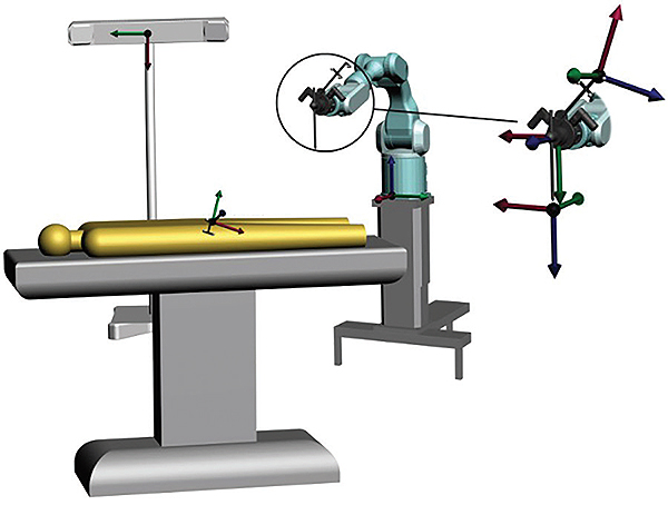
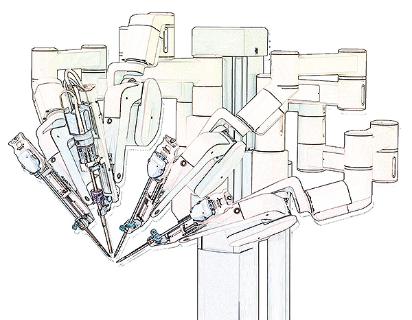
millimeter of error can drastically impact patient outcome. Here, zero-backlash actuators with encoder-equipped gearheads at the robot end effectors let surgeons accurately position equipment.
Consider another example: In electronics assembly, accurate positioning of components during pick-and-place operations can mean the difference between a finished circuit board and expensive pieces of scrap. The gearhead encoder’s accuracy and small size make it suitable for these uses.
MICROMO
www.micromo.com


Leave a Reply
You must be logged in to post a comment.