• Skip to primary navigation
  • Skip to main content
  • Skip to primary sidebar
  • Skip to footer
  • Advertise
  • Subscribe

Motion Control Tips

Automation • Motion Control • Power Transmission

  • News
    • Industry News
    • Editor Blogs
  • Controls
    • HMIs
    • PC-Based Controllers
    • PLCs + PACs
    • Stand-Alone Controllers
    • Software
  • Drives
    • Servo Drives
    • Stepper Drives
  • Encoders
    • Absolute Encoders
    • Incremental Encoders
    • Rotary Encoders
  • Mechanical
    • Bearings
    • Brakes + Clutches
    • Belt + chain
    • Couplings
    • Gears + Gearing
    • Lubrication
    • Shock + Vibration Mitigation
    • Springs + Rings + Seals
  • Linear
    • Actuators
    • Linear Motors
    • Linear Encoders
  • Motors
    • AC Motors
    • DC Motors
    • Brushless Motors
    • Gearmotors
    • Piezo Motors
    • Servo Motors
    • Stepper Motors
  • Systems
    • Conveyors + linear transport systems
    • Gantries + Stages
    • Rotary Tables
    • Grippers + End Effectors
    • Robotics
  • Networks
    • Connections + Sliprings
    • Fieldbuses
    • I/O
    • Sensors + Vision
  • Resources
    • FAQs
      • Motion Casebook
      • Motion Selection Guides
    • Suppliers
    • Video
You are here: Home / FAQs + basics / What are DIN rails for motion applications?

What are DIN rails for motion applications?

May 31, 2019 By Miles Budimir Leave a Comment

Let’s face it — when designing a motion control or automation system, engineers don’t immediately think of enclosures and component mounting. They’re instead concerned with selecting the right type of controllers, motors, actuators, feedback, and networking all of these pieces together. Not top of mind (usually) is how a controller will fit inside of an instrument rack and how it will connect with other components.

DIN rails
An example of components mounted to DIN rails are these fuse blocks from AutomationDirect.

But simply because mounting accessories may not be top-of-list items doesn’t make them any less important and worthy of consideration than any other piece of a properly functioning automation system.

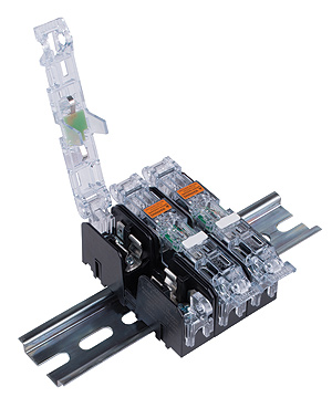
And so we come to the humble DIN rail. DIN is an acronym for Deutsches Institut für Normung, or the German Institute for Standardization in English. The mounting rail dimensions and specifications were at first standardized by DIN and have since become accepted EN and IEC standards applicable globally. A DIN rail is basically a standard for metallic rails inside of equipment racks onto which are mounted control components such as controllers (PLCs, individual controllers, etc), power supplies, I/O and other types of modules. Most if not all component manufacturers accommodate or supply components that fit on standard DIN rails.

They are typically made of a few different materials, with the most common being galvanized steel. Other materials include copper and aluminum. However, the main way DIN rails are classified is according to rail shape and dimensions.  For instance, there are generally considered to be three basic types: the so-called “top hat”, C section and G section.

DIN rails
The “top hat” DIN rail (also known as the TS 35 in the U.S.) showing the 35 mm width dimension and the 7.5 mm depth. (Image via Wikipedia)


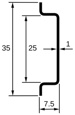
Top hat – The most common is the “top hat” rail, which looks a bit like a top hat in a cross-sectional view. In the U.S. they’re also known as TS 35 rails. The top-to-bottom rail width is 35 mm and lengths can vary. There are two standard depths; 7.5 and 15 mm, with the more common being the 7.5-mm version. There is also a miniature top-hat version with a rail width of 15 mm and a depth of 5.5 mm.

C section – C section rails are 32 mm wide and their cross section is like a C shape. These are older variants of the standard with the top-hat variety being the far more common type. The four common types are C20, C30, C40, and C50, with the number corresponding to the height of the rail in millimeters.

G section – G section rail resembles a “G” in profile, with a deeper recess on one side. This is usually mounted facing down with the smaller recessed side up. G rails are typically used for heavier components such as power supplies.


You might also like

Filed Under: FAQs + basics, Industrial Automation

Reader Interactions

Leave a Reply

You must be logged in to post a comment.

Primary Sidebar

LEARNING CENTER

Design World Learning Center

Motion Control Handbook

“mct
EXPAND YOUR KNOWLEDGE AND STAY CONNECTED
Get the latest info on technologies, tools and strategies for Design Engineering Professionals.

RSS Featured White Papers

  • Robotic Automation is Indispensable for the Logistics Industry’s Continued Growth and Success
  • Reliable Linear Motion For Packaging Machines
  • Polymers Outperform Metals In Precision Gearing

Footer

Motion Control Tips

DESIGN WORLD NETWORK

Design World Online
The Robot Report
Coupling Tips
Linear Motion Tips
Bearing Tips
Fastener Engineering.
Wire and Cable Tips

MOTION CONTROL TIPS

Subscribe to our newsletter
Advertise with us
Contact us
About us

Copyright © 2026 · WTWH Media LLC and its licensors. All rights reserved.
The material on this site may not be reproduced, distributed, transmitted, cached or otherwise used, except with the prior written permission of WTWH Media.

Privacy Policy | RSS