Updated May 2018 by Lisa Eitel || Nailing down the features of a servomotor is a tricky exercise, but the hallmark of any servomotor is the presence of feedback and closed-loop control.
Servomotors provide precise control of torque, speed or position using closed-loop feedback. They can also operate at zero speed while maintaining enough torque to maintain a load in a given position.
Servomotors have several distinct advantages over other types of motors. For starters, they offer more precise control of motion. This means they can accommodate complex motion patterns and profiles more readily.
Also, because the level of precision offered is high, the position error is greatly reduced.
All servomotors have essentially three components; an electric motor, a feedback device, and some type of electronic control.
The electric motor itself can be either an ac or a dc motor. Under the dc heading, brushed dc servomotors are generally less expensive than brushless servos, but do require more maintenance due to the brushes needed for motor commutation.
Brushless servomotors are more expensive than brushed dc motors. Generally, these are used in applications requiring higher torque. Brushless dc servomotors are highly reliable and virtually maintenance free.
However, the drives for brushless dc servomotors are more complex because the commutation is done electronically rather than mechanically as in the brushed dc motor.
Another way to classify servomotors can be as either single-phase or three-phase motors. Motors of the single-phase variety can range from the simple and inexpensive brushed dc motors mentioned above to voice coils for small micro- and nano-positioning applications.
Servomotors also require a form of feedback, often with the feedback device, such as an encoder, built right into the motor frame. The feedback signal is needed by the control circuitry to close the control loop. It is this closed-loop control that gives servomotors their precise positioning ability.
Lastly, the control circuitry typically involves a motion controller, which generates the motion profile for the motor, and a motor drive which supplies power to the motor based on the commands from the motion controller.
Servomotors are used in many different industrial applications from machine tools, packaging machinery, communications and robotics applications to newer applications such as solar panel control and a broad range of automation control applications. The diversity of applications means that servomotors are designed for general-purpose indoor environments but also for specialized situations requiring them to withstand extreme temperatures and pressures outdoors as well as the special demands of food processing industries in washdown environments.
One new option: Integrated Servomotors
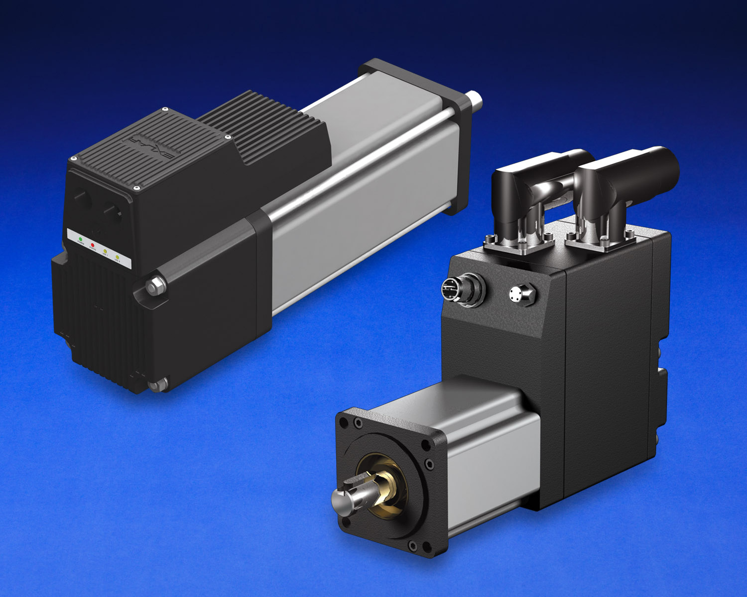
A newer subcategory of servomotor is often called the integrated servomotor. In this type of design, the motor itself is combined with the other essential components of a complete motion control system including the feedback device (generally an encoder), the amplifier or motor drive, a communication port and the motion controller itself.
Such systems are said to offer greater reliability mainly because there are fewer parts to connect together. Also, fewer external connections means less cabling and wiring. Less cabling and wiring reduces costs, as does the fact that the components that one would usually purchase separately such as the motion controller and the drive are integrated into one package.
These integrated servomotors are also designed to be programmed easily and quickly, which can help reduce development times. Communication options range from simple serial communication links such as RS232 or RS485 to more advanced network topologies suited to complex motion control tasks such as CANopen, DeviceNet, or Ethernet protocols.
As with any motor, when selecting an integrated servomotor for an application, the most important step is determining the characteristics of the load. This is why properly calculating the load torque is such an important part of selecting the right motor and designing it into the application. A good rule of thumb to keep in mind is to try and keep the actual operating conditions below the published limits of the motor in order to ensure reliable and long-life operation.
Motor sizing parameters are usually based on the torque curve and moment of inertia of the load. These two factors can help determine the motor’s operating bandwidth. Sets of torque curves depict limits of both continuous and peak torque for the given motor over their full range speed.
There are different types of torque curves, dealing with peak torque and continuous torque as well. Peak torque curves can be derived from dyno testing and represent the point at which peak current limit hardware settings of the drive prevent further torque in an effort to protect drive stage components.
For any mechanical system, if the motor is operating in its optimum range, then the system will be performing at its best. Beyond the motor itself, depending on the specifics of the application it may be necessary to adjust mechanical components such as gear reducers, belts, lead screw pitch or pinion gears in order to achieve optimal system performance.





Leave a Reply
You must be logged in to post a comment.