
Modern servo drives with advanced tuning capabilities — when paired with performance servo motors having high-resolution feedback — can eliminate load-to-motor inertia-mismatch concerns.
By the Kollmorgen engineering staff
The accepted principle of matching motor to load inertia is no longer pertinent with today’s faster motion-control processors and advanced control algorithms. This outdated inertia-matching method of optimizing system dynamics increases costs and adds unnecessary mass in applications where load inertia is high and the continuous torque requirements are low.
The truth is that motor inertia is only one consideration when developing an optimally performing solution delivering good bandwidth and servo stiffness.
As we’ll explore in this article, two elements are key to building high-performance motion systems:
• Mechanisms that are designed to be stiff
• Application components that are suitably sized for the application
Motion systems with these two elements are capable of higher bandwidths, improved move and settle times, and robust dynamic control.
Origin of inertia-matching rules
Inertia matching was believed to address the stable control of a driven load connected to a servo motor. During the 1970s when brush-type servo motors began to replace hydraulics in the machine-tool world, designers calculated the load inertia, torque, and speed requirements based on the expected performance of the machine. Then when selecting a motor to meet the needed torque and speed requirements, if the motor to load inertia wasn’t close to a 1:1 match, engineers used one of two options:
• They’d swap in a motor having higher inertia
• They’d use a gearbox to reduce the reflected inertia seen by the servo motor
Both of these approaches work but increase the system cost. Though optimal power transfer does occur when inertias are matched, that doesn’t guarantee an efficiently operating system. Ideally, total system inertia should be reduced to expend less energy. However, a larger motor increases the torque required to accelerate the added motor-rotor inertia.
There are still other considerations to application sizing. During the initial transition of hydraulic to electric motors, quick analysis of complete mechanical and control systems was limited by available technology.
Of course, the construction of closed-loop servo systems includes components that can dramatically affect machine performance — including the motor, attached feedback device, coupling to the load, and the capabilities to tune the servo loops. Today’s systems can provide good performance by letting design engineers tune the servo loops to operate within the target bandwidth and servo stiffness, which in turn optimizes the response to controller commands … even while minimizing overshoot. In these systems, the servo motor is controlled by a servo drive using current, velocity, and position loops. Each loop is tuned to create an enhanced system response by ensuring:
• System stability
• Quick reactions to torque or velocity disruptions
• Smooth operation.
In contrast, the tuning systems of the past forced design engineers to tune servo loops using discrete components and potentiometers. That meant engineers had to adjust loop gains largely through experimentation. Limited analytical tools and processing power combined with discrete components demanded a close inertia match between motor and load.
Unfortunately, even as processors and analytics improved (and digitally tuned servo loops were developed) the old demand for a 1:1 match continued to perpetuate.
Technological advancements first brought (limited) inertia-matching rule changes
With the advent of brushless motor technology, high-energy NeFeB magnets, and digital tuning loops, the inertia-matching protocol met with new complications. High-energy magnets located on the rotor made for motor inertias that were far smaller than those of comparable brush-type motors. So, motors meeting the application’s needed continuous and peak-torque capabilities had higher load-to-motor inertia mismatches. It’s true that servo-drive digital tuning loops made it considerably easier to adjust gains and filters to provide stable control. However, the low processor speeds, low-resolution feedback devices, and other limiting factors of the time often led to the development of brushless-motor options with excessive inertia.
Increased processing power allowed the complex analytics to create accurate mathematical modeling and simulation of system responses. So now, advanced tools integrated into today’s servo drives create interactive analytics of complex mechanical systems. For design engineers, that simplifies the process of optimizing servo systems.
Advanced analytics also let machine builders understand (in detail) the precise fingerprint of the mechanical system … and how to best address performance limitations.
Compliance — the menace of high-bandwidth solutions
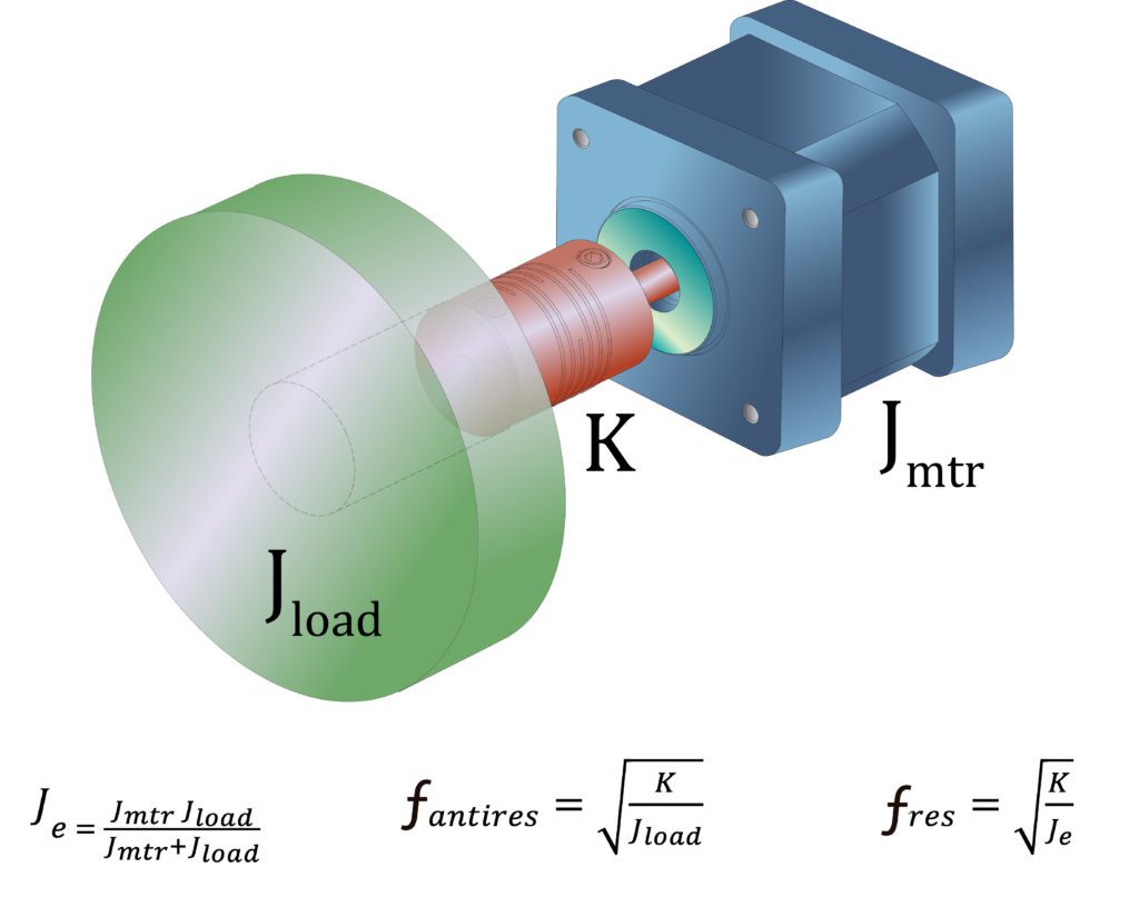
Compliance in mechanical systems is the natural springiness of the power-transmission components between the driven load and the motor. This compliance creates delayed response times — in turn reducing system bandwidth. What happens if a design engineer introduces a large inertia mismatch into such a system? Well, the problem of compliance is only magnified.
Case in point: Consider a motion design having a small motor capable of output torque sufficient to move an exceptionally large load … but the motor and load are connected via a coupling. When the small motor quickly applies torque to the large load, the larger load will hesitate to respond, because an object at rest tends to stay at rest. The delay is a result of coupling compliance between the motor and load that introduces windup before the load begins to move.
Unfortunately, as the load eventually syncs up with the motor, the large inertia overshoots the target speed … causing the smaller motor to adjust by slowing down. When the system adjusts the large inertia’s overspeed, the target speed is again passed — triggering the small motor to adjust once more. This continued cycling creates resonance and an unstable system.
Most mechanical systems can be mathematically modeled and simulated using various excitation frequencies to quickly identify the frequency response — the frequencies at which a resonance occurs. System bandwidth can never exceed the initial anti-resonance point of the system. The goal of increasing bandwidth is to push the initial resonance frequency higher by identifying and addressing the cause of the resonance. In a compliant system, as the compliance or springiness increases, the frequency of the initial resonance point is at a relatively low Hertz (Hz) value — which in turn decreases system bandwidth.
In contrast, when the driven load is directly coupled to the motor to minimize compliance, the mismatch is mitigated — increasing the initial resonance frequency and creating a higher-bandwidth system.
Increased stiffness and reduced system inertia
As mentioned earlier, mathematical models representing a mechanical system show that the ultimate solution for a higher bandwidth and cost-effective system is to increase the mechanical stiffness … and to reduce total system inertia.
Consider a direct-drive solution in which load directly couples to the motor with near-zero compliance. Precisely controlling the system with good bandwidth can be achieved even with inertia mismatches exceeding 1,000:1.
In an extremely stiff (non-compliant) system, the servo system should be sized to provide the necessary torque to move the system inertia in the manner needed by the specific application. Of course, because direct-drive solutions are not suited to all applications, most motion system designs will include power-transmission components that do in fact introduce some compliance. But advanced analytical tools on some of today’s servo drives readily identify the compliant elements that reduce system performance.
This chart illustrates the improved performance and cost savings when engineers stop using the old inertia-matching approach in favor of using increased mechanical stiffness and reduced inertia:
| Axis | Original Jm (kg-cm2) |
New Jm (kg-cm2) | Load inertia (kg-cm2) | Original mismatch | New inertia mismatch | Increase | Cost savings |
| X | 120 | 67.7 | 256.75 | 2.14 | 3.79 | 77% | 17% |
| Y | 17 | 4.58 | 9.56 | 0.56 | 2.09 | 273% | 34% |
| Z | 121.6 | 80 | 29.4 | 0.24 | 0.37 | 54% | 17% |
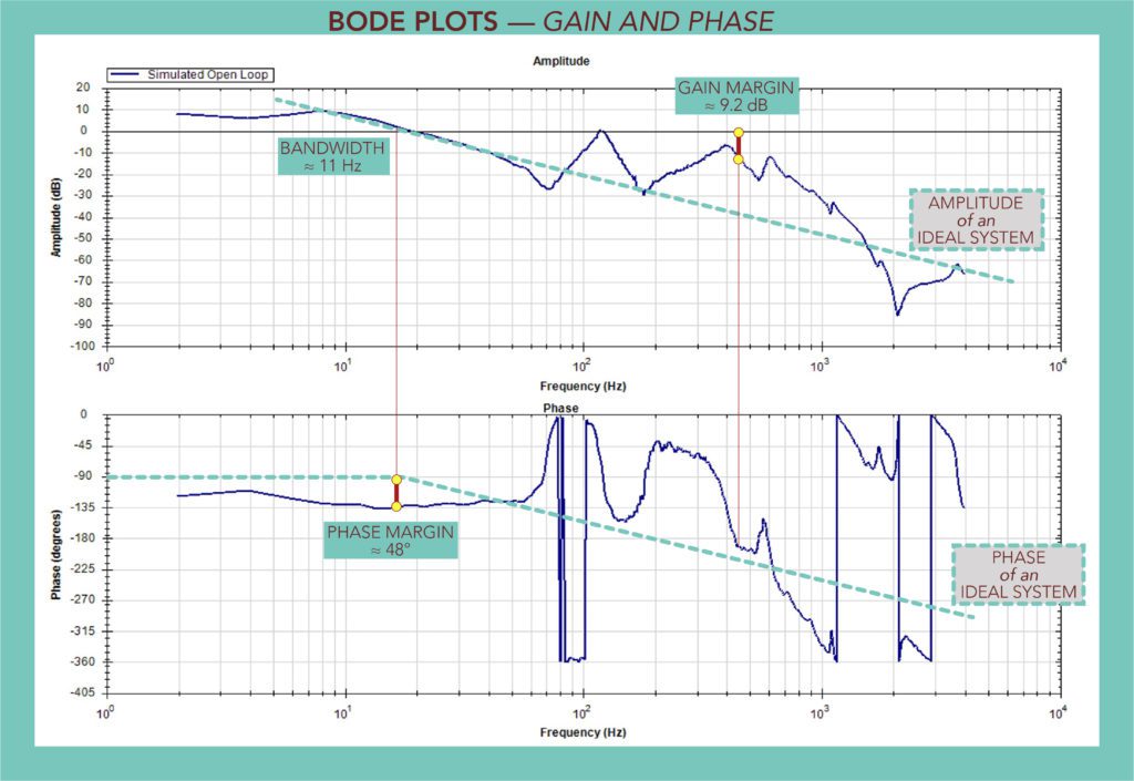
Bode plots of motion system designs
The Bode plot is a powerful analytical tool consisting of two charts illustrating the frequency response of an injected signal to identify the amplitude and phase lag of the system.
Bode plots also provide clues about a system’s inertia mismatch, number of connected bodies, and friction levels … and can identify the system’s open and closed-loop bandwidths, phase and gain margins, and resonance frequencies. This information is invaluable for tuning the system to deliver optimal performance. Usually such optimization is done through adjustments to loop gains, the installation of various digital filtering modes, and (in some cases) slight design changes to the system’s mechanics.
Refer to the Bode plot example accompanying this article. Using this Bode plot, we can determine the open and closed-loop bandwidths … as well as the associated gain and phase margins. The bandwidth is represented by the frequency at which the open-loop plot reaches 0 dB — here at about 11 Hz. The phase margin is the number of degrees above -180° (about 48°) and the gain margin is the amplitude measurement corresponding to a phase of -180° — about 9.2 dB.
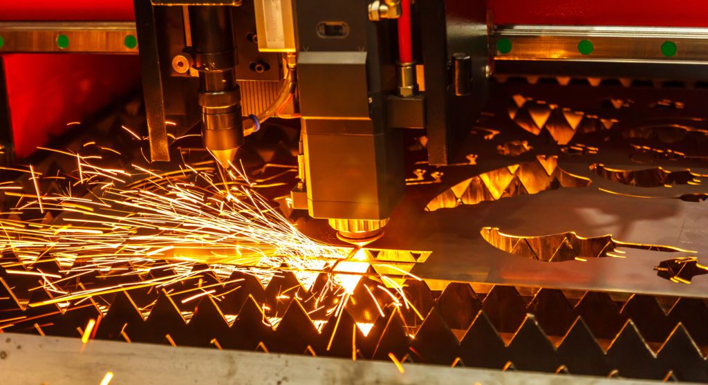
Just consider one real-world application example illustrating how to successfully optimize performance along with cost by applying improved system stiffness to the solution — without concern for inertia mismatch …
A three-axis laser-cutting machine was initially designed (and its axes’ motors selected) using the inertia-matching approach. A redesign aimed to reduce the machine’s cost and boost its performance. A review of the application requirements showed that alternate motor solutions could increase the system resonance point to allow additional gain and phase margins and improved stability.
The new servo motor used in the improved version of the laser-cutting machine reduced the total system inertia, provided higher power density in a smaller package, and increased the stiffness of the machine axis having a large shaft diameter — the one having a high resonant frequency. This increased shaft stiffness reduced compliance which improved performance.
Kollmorgen | kollmorgen.com


Leave a Reply
You must be logged in to post a comment.