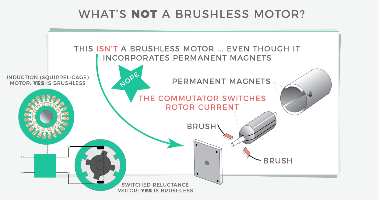
Brushless motors are any permanent-magnet motors, switched-reluctance motors, or induction motors that omit the use of commutator and brushes for commutation. But one motor type is usually implied when engineers use the term brushless motor — the permanent-magnet design. Also called electronically commutated or EC motors, these don’t suffer from brush wear or arcing … but do need electronic current-phase commutation. Basically, brushless dc motors are similar to shunt-wound motors except field flux comes from magnets instead of current through a winding.
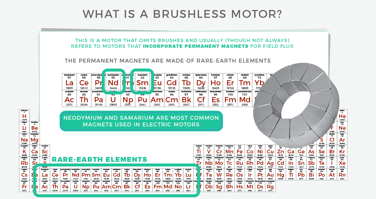
Brushless motor designs incorporate one of three magnet types. Ferrite or ceramic magnets are relatively weak but common because they resist demagnetization and corrosion resistance. Plus they’re low-cost. Ceramic magnet only work up to 250°C, though magnetism returns when they’re cooled back down. Warning though — running at -20°C or colder can spur permanent loss. The other two magnet types in brushless motors are rare-earth types.

More specifically, samarium cobalt (SmCo) magnets excel in hot applications, even up to 550° C. The third option are neodymium magnets — which find use in industrial brushless motors as well as motors in electric cars. Low-coercivity neodymium magnets can lose strength above about 80° C but some variants survive up to 220° C. One other drawback is that neodymium magnets can corrode and then crumble … so they are usually treated with a protective coating. Nickel plating or two-layered copper-nickel plating are common here.
Brushless motor (EC motor) naming caveats
Note that there are some naming-convention caveats: There are permanent-magnet motors with brushes (for mechanical commutation) and some call these PMDC motors.
Motors called brushless DC motors have permanent magnets so they’re technically PM synchronous motors but run off ac from a dc bus and electronic inverter. Brushless DC motors, as they are called, don’t run directly from ac lines. They can — with the proper drives powering them —replace dc brush motors (paired with drives) in closed-loop applications. Some engineers argue “brushless DC motor” is a misnomer.
To be clear, brushless motors with armature (stator) magnets exist — and are powered by current to the rotor through a commutator — but motors with magnets on the rotor are far more common. With the ever-falling cost of electronics, today’s permanent-magnet brushless motor-drive systems are often less costly than comparable brush-motor-drive systems. Most brushless motors are used in fractional-horsepower applications, though higher power uses are on the rise.
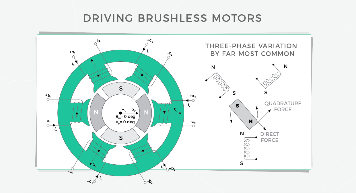
Output torque in brushless motors is proportional to stator current over the motor’s speed range. Motors with permanent magnets are smaller, lighter, and more economical to run than many brush motors. While brushless motors come in single-phase and two-phase variations, three-phase motors are by far most common.

One simple way to control brushless motors is with trapezoidal commutation. Here current is metered through the motor’s phases two at a time with the third unpowered. Hall sensors track rotor position and enable the switching between phases in the correct sequence. The main limitation is that the phase current vectors can only have six discrete directions. In contrast, sinusoidal brushless-motor control sinusoidally drives the three motor windings with three currents for smooth rotation of the combined current space vector — always in the rotor quadrature direction and always with a set magnitude. The only catch is that sinusoidal commutation requires a finer measure of rotor position than Hall sensors, using an encoder, for example, which adds cost.
Taking controls a step further is field oriented control — which sidesteps the limitations of controlling time-variant motor currents. This limitation is worst when speeds and frequencies rise from limited PI-controller bandwidth. Instead, field oriented control directly controls the current-space vector in the D-Q (that’s direct and quadrature, not ice cream) rotor reference frame. Ideally that’s a vector fixed in direction (AKA quadrature) relative to the rotor’s magnetic poles … no matter the rotation. The current-space vector in the D-Q reference frame is static so the PI controllers run off dc instead of sinusoidal signals. This isolates them from time-variable winding voltages and currents — which in turn avoids controller frequency-response limitations among other things. That way the quality of current control is immune to the effects of motor rpm. For more videos like this, visit designworldonline.com and click on videos.

Leave a Reply
You must be logged in to post a comment.