
Using software to size motion designs is rewarding because engineers can efficiently predict which products are suitable for the application at hand. But key considerations (sometimes missed) when selecting a servo amplifier are those of dynamic braking and regenerative resistor braking.
By Sixto Moralez • Regional Motion Engineer
Phil Drexler • Regional Motion Engineer | Yaskawa America Inc.
Design engineers who are running sizing calculations for a servo application should consider dynamic braking as well as regenerative braking requirements when selecting a servomotor and digital amplifier for that design. The terms are sometimes used interchangeably, as both types of braking involve processing regenerative energy. But as we’ll explore, there is a subtle difference between dynamic braking and regenerative braking.
We’ll also explore how to leverage the benefits of servo amplifiers that include dynamic-braking provisions.
What is dynamic braking?
If the servo axis suddenly turns off while the servomotor is operating and the axis is running at some non-zero velocity — for example, due to loss of power or an emergency stop triggered by an alarm — the digital servo amplifier can no longer control the servomotor. That means unless there’s some mechanism to prevent coasting, that axis will indeed coast until all of the kinetic energy from the load and its own rotating inertia is expended.
Because mechanical losses in the system usually expend only a small amount of energy, the coasting distance can be quite long. This long stopping distance may spur equipment damage and/or personal injury.
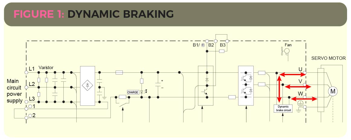
Here, dynamic braking is helpful. It uses the regenerative power produced by the rotating servomotor to brake the servomotor. The servomotor’s kinetic energy converts to electrical energy and is expended as heat (through resistors) to stop the servomotor. In short, dynamic braking is the quick stopping of a spinning servomotor by connecting resistance between the servomotor’s terminals U, V, and W.
Consider some examples of when the dynamic braking circuit might be activated.
Servo alarm: With default parameter settings, the digital servo amplifier will apply dynamic braking to stop the servomotor when a Group 1 alarm occurs. In some cases, users can modify the setting of this parameter by using drive-manufacturer software.
Over-travel: Hitting the over-travel limit switches in the forward or reverse direction.
Main power off: Turning off the main power supply to the digital servo-amplifier circuit or servomotor.
What is regenerative energy?
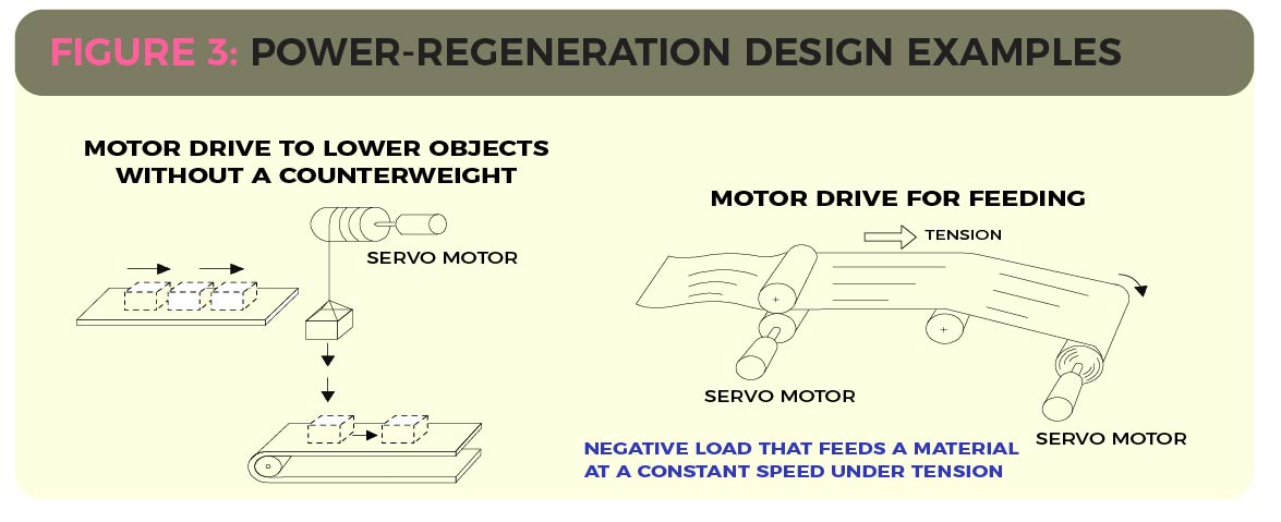
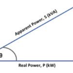
In a servomotor system under the control of a digital servo amplifier, when the output torque of the servomotor is opposite the direction of the shaft rotation, the motor acts as a generator … and the resulting energy flows back into the drive. The energy returned to the drive is regenerative energy. Three examples of when regeneration occurs during motor operation are decelerating a moving load; lowering a vertical load; and an overdriven nip roll.
That leads to the next question — what is regenerative resistor braking? Here, regenerative energy is returned to the drive during deceleration because the motor must apply torque opposing the rotation’s direction to stop the load.
For example, when lowering a load without a counterweight, the force of gravity drives the load down, and the motor must apply torque opposite the direction of downward rotation to control the load.
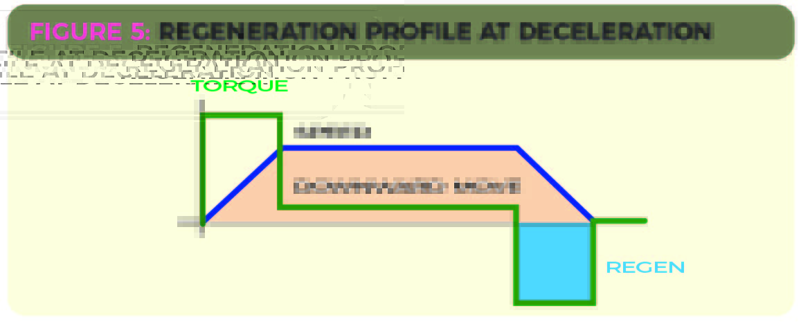
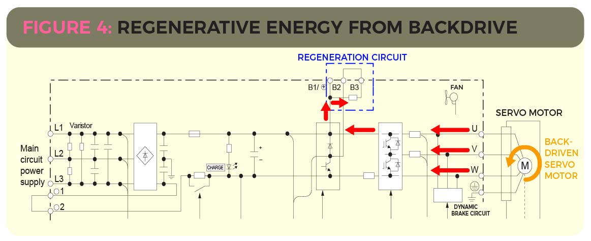
Likewise, in the case of an overdriven nip roll, the motor must apply torque opposite the direction of rotation. In both cases, regenerative energy returns to the drive. Whenever regenerative energy returns to the digital servo amplifier, the bus capacitors absorb the energy … and the dc bus voltage rises.
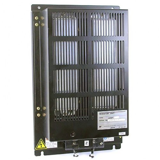
Of course, if there’s a large amount of energy, the energy must dissipate to protect the drive. A braking transistor turns on to let current flow from the bus through a braking resistor. This process is known as regenerative resistor braking.
Digital servo amplifiers from some manufacturers have built-in resistors to dissipate some regenerative energy … though if the amount of regenerative energy processed by the built-in resistor is exceeded, the design will need an external regenerative resistor.
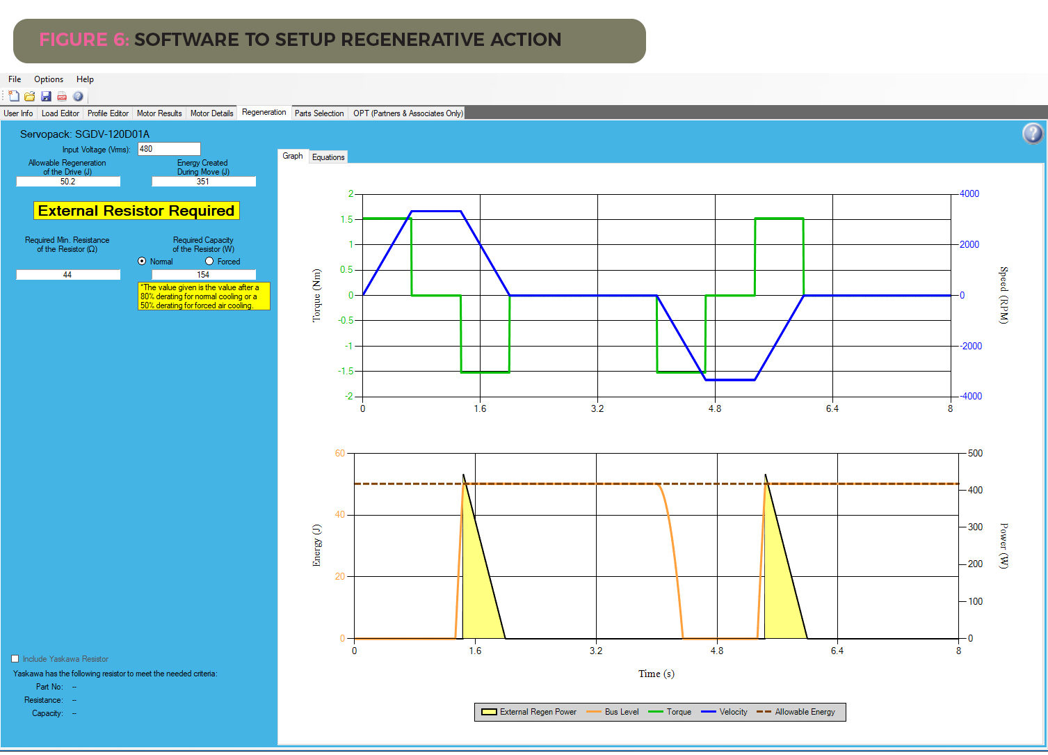
Word to the wise: Use (full-featured) servo-sizing software
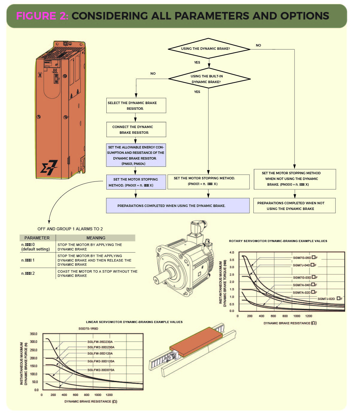
Using servo-sizing software from some manufacturers to size motion applications lets engineers verify the regenerative and dynamic braking parameters specific to the application. Here the engineer can enter details about the system mechanics, motion profile, and other details such as input voltage and the servomotor brake parameters. Such software ultimately identifies one or multiple servomotor and digital servo amplifier combinations that will work in the application at hand. Some such software can even return speed-torque curves and regeneration values for each machine-build option.
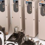
Though no one size fits all, servo systems verified upfront for dynamic braking and regenerative resistor braking will deliver longer life. Yaskawa’s networkable digital amplifiers (Sigma-7 Series Servopacks) include dynamic braking provisions in their amplifiers. For more information, visit yaskawa.com/products/motion/sigma-7-servo-products.
Leave a Reply
You must be logged in to post a comment.