• Skip to primary navigation
  • Skip to main content
  • Skip to primary sidebar
  • Skip to footer

Motion Control Tips

Automation • Motion Control • Power Transmission

  • News
    • Industry News
    • Editor Blogs
    • Video
  • Controls
    • HMIs
    • PC-Based Controllers
    • PLCs + PACs
    • Stand-Alone Controllers
    • Software
  • Drives
    • Servo Drives
    • Stepper Drives
  • Encoders
    • Absolute Encoders
    • Incremental Encoders
    • Rotary Encoders
  • Mechanical
    • Bearings
    • Brakes + Clutches
    • Belt + chain
    • Couplings
    • Gears + Gearing
    • Lubrication
    • Shock + Vibration Mitigation
    • Springs + Rings + Seals
  • Linear
    • Actuators
    • Linear Motors
    • Linear Encoders
  • Motors
    • AC Motors
    • DC Motors
    • Brushless Motors
    • Gearmotors
    • Piezo Motors
    • Servo Motors
    • Stepper Motors
  • Systems
    • Conveyors + linear transport systems
    • Gantries + Stages
    • Rotary Tables
    • Grippers + End Effectors
    • Robotics
  • Networks
    • Connections + Sliprings
    • Fieldbuses
    • I/O
    • Sensors + Vision
  • FAQs
    • Motion Casebook
    • Motion Selection Guides
  • Suppliers
You are here: Home / Mechanical PT / Brakes + Clutches / Example of tight torque-limiter integration for overload protection

Example of tight torque-limiter integration for overload protection

November 8, 2017 By Lisa Eitel Leave a Comment

12 days after getting details of the application problem, Mach III had designed, manufactured, and delivered five complete torque-limiter/pulley assemblies to fix it.

Ideally engineers would anticipate the need for overload protection in a drivetrain and include it in the original design. But overload problems often only appear after equipment is in use. Such designs require torque-limiter retrofits, even if existing assembly geometry is tight. Making the issue more challenging is that end users often want a solution right away.

In one such aircraft-wing assembly application, an arm to position components had problems with overload shortly after going into use. Arm articulation is through a timing-belt pulley at a pivot point, which in turn is driven by a belt engaging the motor output shaft. Extra load on the wing assembly transferred backward through the arm to the motor. Adding a torque limiter was the clear solution, but there was only one inch of axial space available between the frame and pulley.

No torque limiters thin enough to fit could deliver the needed 530 lb-in. of required torque. It appeared that the only option was to redesign and rebuild the arm — a costly and time-consuming proposition. Instead, the aircraft-assembly operation found an option for an emergency retrofit — so in 12 business days from initial inquiry to delivery, got a new component for the kinematic system that combines the drive pulley and torque limiter. That addressed the space constriction while still delivering 760 lb-in. of torque.

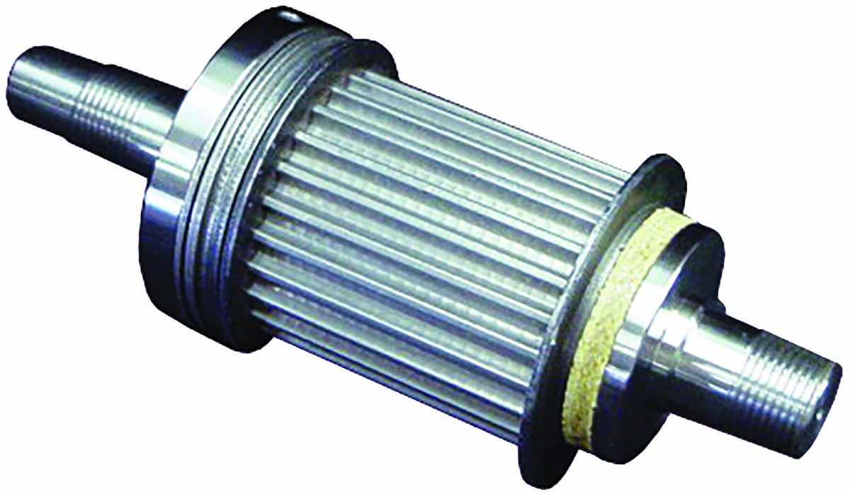
Engineers from Mach III Clutch Inc. designed the specialty component to combine the timing-belt pulley and torque limiter into one component that uses less than one inch of available axial space. Nothing in the rest of the design had to be moved; even the belt position was maintained.

Mach III also expedited production of the custom component to keep the maker of the assembly arm out of trouble with the end user.
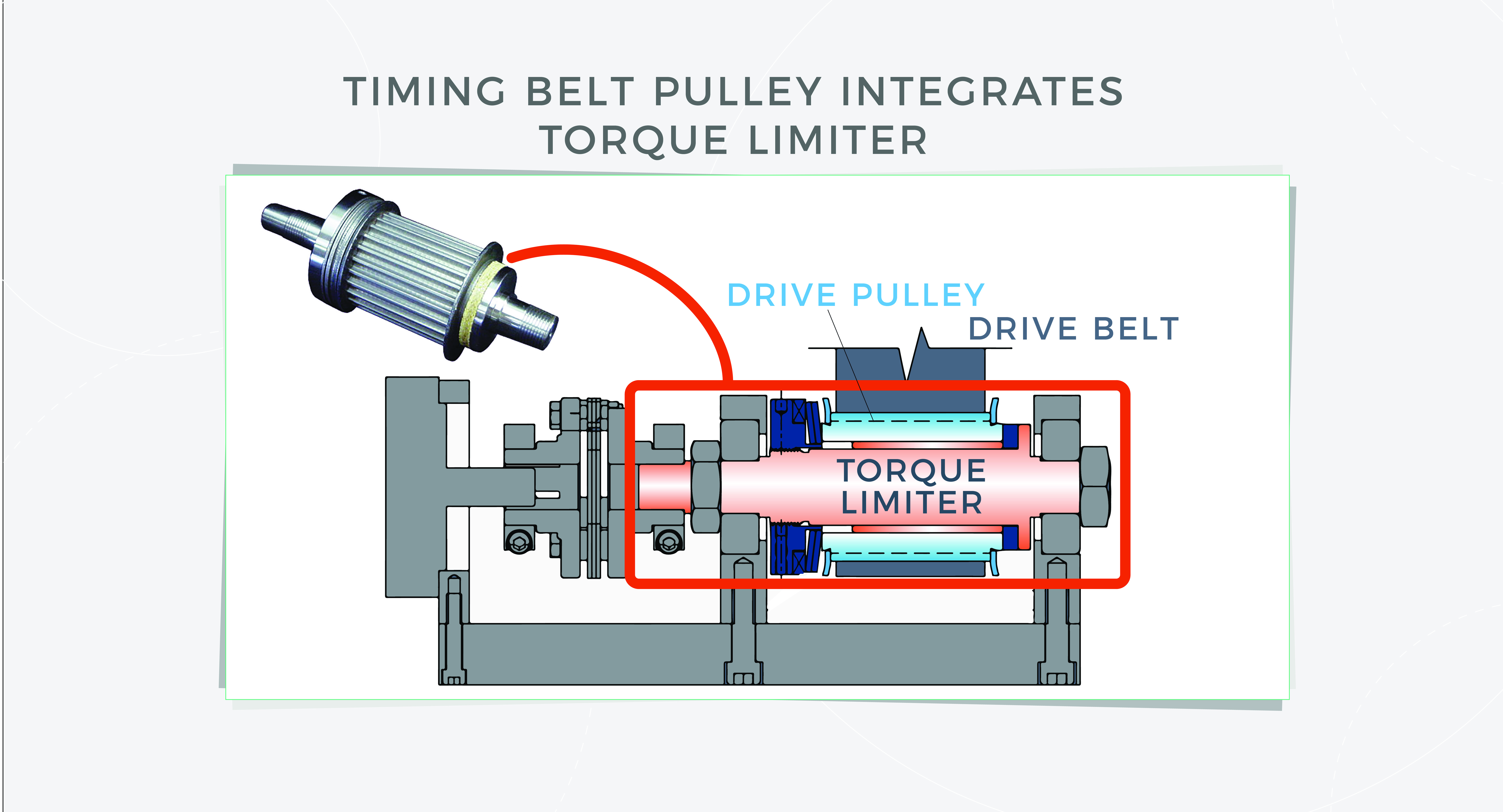
Engineers from Mach III Clutch Inc. designed a specialty component to combine a timing-belt pulley and torque limiter into one component. This addressed a serious overload problem in a piece of aircraft-assembly equipment identified after operations had begun.

You may also like:


  • Networking for motion: Update on five realtime Ethernet-based protocols

  • What are common modes of industrial clutch and brake engagement?

  • Motion trends third edition: Industrial clutch and brake technologies

  • Updated: Trends in electric motors Part V — Research laboratories…

  • Updated: Trends in electric motors Part II — Scott Evans…

Filed Under: Brakes + Clutches, Featured, Integrated Motion Systems, Mechanical PT Tagged With: machIII

Reader Interactions

Leave a Reply

You must be logged in to post a comment.

Primary Sidebar

POWER TRANSMISSION REFERENCE GUIDE

DESIGN GUIDE LIBRARY

“motion
Subscribe Today

RSS Featured White Papers

  • Specifying electric rodless actuators: Ten tips for maximizing actuator life and system performance
  • The truth about actuator life: Screw drive survival
  • Top Ten Tips: How to specify electric rod-style actuators for optimal performance, reliability and efficiency

Footer

Motion Control Tips

DESIGN WORLD NETWORK

Design World Online
The Robot Report
Coupling Tips
Linear Motion Tips
Bearing Tips
Fastener Engineering.

MOTION CONTROL TIPS

Subscribe to our newsletter
Advertise with us
Contact us
About us
Follow us on TwitterAdd us on FacebookAdd us on LinkedInAdd us on YouTubeAdd us on Instagram

Copyright © 2022 · WTWH Media LLC and its licensors. All rights reserved.
The material on this site may not be reproduced, distributed, transmitted, cached or otherwise used, except with the prior written permission of WTWH Media.

Privacy Policy | RSS