
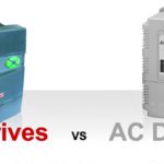
Using proportional-integral-derivative (PID) control with variable frequency drives (VFDs) is common when a process set point—such as temperature, pressure, flow, or speed—needs to be precisely controlled. In fact, many VFDs are now supplied with an integrated PID controller.
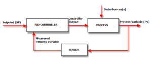
Image credit: Control Solutions, Inc.
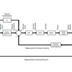
PID controller terms
Configuring the PID parameters for fast response and minimum overshoot (referred to as tuning the drive) is typically an iterative process, as each variable has an effect not only on the system performance, but also on the other variables. Regardless of the tuning method used, the first step in configuring PID parameters is to understand what each parameter means and how it affects the system.
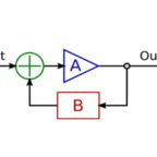
P = Proportional
The proportional component of the PID controller determines how much the output will change, based on the error between the feedback and the set point. With the proportional component, there is a linear, immediate relationship between the error and the response (output).
Note that in servo tuning, the P component is often referred to as proportional gain, whereas in process applications, the P component is typically referred to as proportional band. These two terms are the inverse of each other: Proportional Gain = 100 / Proportional Band. An increase in the proportional gain will yield a larger output change for a given error. In contrast, increasing the proportional band yields a smaller output change for a given error.
I = Integral
Where the proportional term considers only the current state of the error at the time of the controller calculation, the integral term monitors the error over time and uses the error history to determine how quickly the output should change. Integral control works to eliminate the offset that results from the proportional control.
Integral gain is given in repeats per minute, indicating how aggressive the integral action is. However, in process industries, the integral term is often referred to as “reset rate” or “repeat rate,” which is expressed in minutes per repeat. As the inverse of integral gain, a high value for the repeat rate decreases the aggressiveness of the integral component.
The proportional and integral gains work in conjunction to quickly move the process variable to the set point without overshooting. As the process variable moves toward the set point, the proportional gain output decreases, but the integral gain output increases because the process variable has not fully reached the set point. Only as the process variable gets close to the set point does the integral gain output begin to decrease.
Image credit: Industrial Controls
D = Derivative
Derivative control determines the output based on the rate of change of the error. Its purpose is to limit overshoot and dampen system oscillations. Derivative gain essentially anticipates errors or upsets as they begin and reacts quickly to correct them.
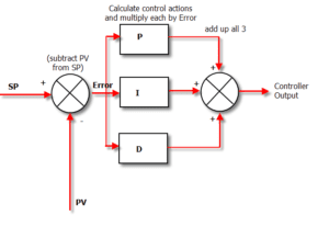
Image credit: Control Solutions, Inc.
PID tuning methods
Because every process is different and has its own, specific behavior requirements, PID control tuning is an inexact science. There are several methods for tuning a PID controller, but they all use, to some extent, experimental methods to determine the behavior of the system and the appropriate control parameters to achieve the desired performance.
Ziegler-Nichols Method
The Ziegler-Nichols method is a common tool for tuning PID controllers. It begins by setting the I and D terms to zero. Then, the proportional gain is increased (or, the proportional band is decreased) until the system reaches a stable oscillation point, referred to as the “ultimate gain,” Ku. The ultimate gain is used in conjunction with the oscillation period, Tu, to determine the proportional gain, integral time, and derivative time, per the Ziegler-Nichols equations.
Cohen-Coon Method
Another popular method for PID tuning is the Cohen-Coon method. This method is better suited than Ziegler-Nichols for self-regulating processes, or those that will stabilize at a point of equilibrium. It begins with a process that has settled, and then conducts a step change test to determine the process gain, dead time, and time constant. The process gain, integral time, and derivative time are determined based on these values and the Cohen-Coon tuning rules.
Manual Tuning
Of all the tuning methods—including Ziegler-Nichols, Cohen-Coon and beyond—the most popular is probably manual tuning. Manual tuning typically begins with a procedure similar to the Ziegler-Nichols method, by setting the integral and derivative terms to zero and increasing the proportional term until stable oscillation is achieved. The integral value is then adjusted until the steady-state error reaches an acceptable level. Then the derivative value (if used) is adjusted until the system has a satisfactory response to disturbances.
The goal of control loop tuning is to achieve low (or no) steady-state error, fast response, and minimal overshoot. Achieving all three at the same time is rarely a realistic goal, but careful tuning of the control parameters can provide the best performance for the process requirements.
Leave a Reply
You must be logged in to post a comment.