
Servo motors are used in closed loop systems and operate based on error feedback—the comparison of a target value to the value actually reached by the motor/load. Because mechanical systems have inertia and compliance, the target value is rarely achieved on the first position command—hence, the need for feedback and correction commands. Servo tuning is a method of adjusting the feedback to determine how hard the system tries to correct the error.
The process of servo tuning means tweaking the various gains and motion parameters in the servo controller so that performance is optimized—i.e. the motion is smooth, with little or no audible noise during and after the motion, and with little or no position error after the commanded motion is completed. In other words, the goal of tuning is to achieve the fastest response from the system, while avoiding or minimizing overshoot of the target value (typically either position or velocity).
Auto-tuning
Most vendors of servo controls offer an “auto-tune” option in their motion control software. Auto-tuning uses the servo drive and controller to test the system at multiple frequencies and set the tuning parameters (often more numerous than those used for manual tuning) to achieve the best response. However, auto-tuning isn’t always able to produce the most optimized motion, especially in highly dynamic systems. This is where manual tuning comes in.
Manual tuning
There are several methods for manually tuning a servo motor, but the most widely used method is by far the PID algorithm. A PID algorithm is responsible for generating the level of the command that is sent to the servo drive (aka servo amplifier). It is effectively the correcting factor between the servo controller output and the performance of the motor and load. When a discrepancy is detected based on the system feedback, the PID algorithm generates a command to correct the error.
As its name implies, the PID algorithm is made up of three components:
P = Proportional Gain (Kp)
Proportional gain is related to the system stiffness. The level of Kp determines the command voltage (restoring force) that is applied to overcome position error. The term “proportional” gain comes from the fact that the restoring force is directly proportional to the position error.
I = Integral Gain (Ki)
Integral gain provides a restoring force during the end of the move to “push” the axis to a point of zero positioning error. It is termed integral gain because it integrates (accumulates) the position error. The longer the error exists, the larger the integral becomes.
In conjunction with integral gain, an integration limit is specified. The integration limit determines the maximum value of the command output that is used to correct the static position error, thereby preventing oscillations and instability.
D = Derivative Gain (Kd)
Derivative gain is the damping on the system. It can be thought of like a shock absorber, reducing overshoot and oscillations. Derivative gain determines the amount of restoring force proportional to the rate of change (derivative) of the position error.
An important companion to the derivative gain is the derivative sampling period (Td). The sampling period specifies how often the position error derivative is calculated. A higher derivative sampling period can improve dampening and increase stability.
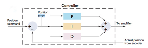
Image credit: Performance Motion Devices, Inc.
Servo tuning can be achieved through a variety of procedures, but the most common method is to begin by increasing Kp until the system overshoots the target (the system is underdamped). Then Kd is increased until the system becomes critically damped (a balance between fast response and low overshoot). Next, Kp and Kd are increased to the maximum amounts that maintain a critically damped response.
Once Kp and Kd are determined, Ki is set. The integral gain helps remove the last bit of error from the system, but, unlike Kp and Kd, it should be kept as low as possible to prevent the system from becoming unstable.
There are three main characteristics that that help determine when a system is properly tuned. The first is overshoot, or how much the target position is exceeded. Next is response time, which is the time the system takes to reach a specified percentage of the target value. Also important is settling time, or the time for the target value to be “settled” within a certain percentage.
Servo tuning is not an exact science—there is no one “right” set of tuning parameters for any given application. The best tools are experience, close observation of the system as parameters are adjusted, and patience for a trial-and-error approach.
Feature image credit: National Instruments
Leave a Reply
You must be logged in to post a comment.