Image credit: Monolithic Power Systems
The primary distinction between brushless DC (BLDC) motors and brushless AC (BLAC) motors is their back EMF waveform. BLDC motors typically have a trapezoidal back EMF, while BLAC motors (also referred to as permanent magnet synchronous motors, or PMSM) have a sinusoidal back EMF. The shape of a motor’s back EMF is important, because it determines what type of drive current and commutation method should be used.
BLDC motor construction
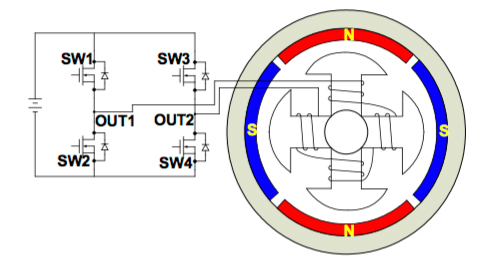
In a BLDC motor, the rotor consists of permanent magnets, and the stator has steel laminations with windings through axial slots. The windings are wound in a trapezoidal fashion and produce a trapezoidal back EMF.
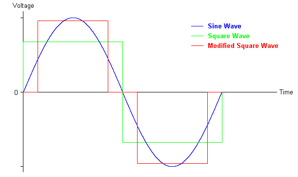
For the best performance, the drive current should match the back EMF waveform, so BLDC motors should be driven with trapezoidal waveforms (direct current). Trapezoidal drives are sometimes referred to as square-wave drives, although true square waveforms are rarely used due to their sharp transition between positive and negative values. Instead, modified square, or quasi-square current is used.

Motor terminology can be tricky. A common way to categorize motors is by their input voltage: AC or DC. But many engineers argue that brushless DC (BLDC) motors are actually AC motors, because they are driven by DC voltage that switches from one stator coil to the next, generating an alternating (hence, AC) trapezoidal or quasi-square waveform.
Another way to classify motors is by their back EMF profile. BLDC motors are referred to as trapezoidal motors, since they produce trapezoidal back EMF, and BLAC motors (aka PMSM) are referred to as sinusoidal motors since they produce sinusoidal back EMF. But, as discussed below, the back EMF of a BLDC motor is not truly trapezoidal in shape. In reality, its shape is more sinusoidal. This is why BLDC motors can use trapezoidal or sinusoidal commutation.
Trapezoidal commutation in BLDC motors
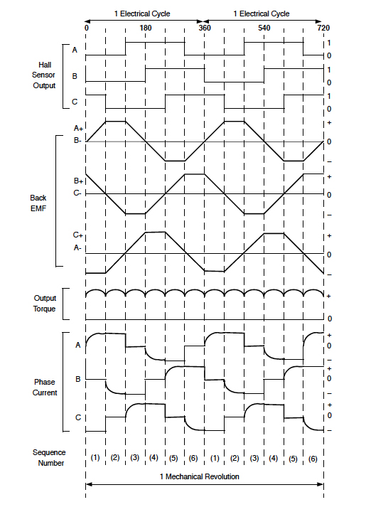
Trapezoidal (aka six-step) commutation is common in high-speed applications or when higher starting torque is required. Trapezoidal commutation is also less costly than other methods, due to its simple control algorithms. In most applications, the rotor position is determined by three Hall-effect sensors that are mounted on the stator, 120 degrees apart. When the rotor passes over the sensors, they produce either a high or a low signal to indicate which rotor pole (N or S) is passing over. The change from high to low (or low to high) of the three Hall sensors gives rotor position information every 60 degrees, meaning that six steps are needed in order to complete one electrical cycle—thus, the term “six-step commutation.” The correct commutation sequence is determined from the combination of the Hall sensor signals.
Trapezoidal commutation can also be performed based on the motor’s back EMF, which allows the elimination of Hall sensors. In a typical three-phase BLDC motor with trapezoidal current, one winding is positive, one winding is negative, and one is open. The open winding can be used to detect the zero-crossing point of the back EMF, which corresponds to what would be a signal change in a Hall sensor. However, the back EMF is proportional to motor speed. This means that at very slow speeds (and especially at startup), the back EMF will be very low, so the motor must be started in open-loop mode until sufficient speed and back EMF are generated. At that point, the controller can be switched to back EMF sensing for commutation.

Image credit: Microchip Technology Inc.
Other commutation methods for BLDC motors
The downside of trapezoidal (six-step) commutation is that it results in torque ripple at each step of the commutation (every 60 degrees). And although in theory, the BLDC motor’s back EMF is trapezoidal, in reality, the back EMF waveform is not purely trapezoidal. Inductance in the motor smooths the back EMF into a more sinusoidal shape. And since the back EMF is more sinusoidal than trapezoidal, it is possible to use sinusoidal commutation with BLDC motors. This requires the addition of an encoder or resolver to accurately track the rotor position, which adds cost to the system, but it results in significantly reduced torque ripple.
Another option is to use field oriented control (FOC). This is a method in which the current vector (magnitude and direction) is determined relative to the rotor, rather than on the basis of sine waves, as is done in sinusoidal commutation. While sinusoidal commutation has low efficiency at high speeds, FOC provides high efficiency across a wide speed range, as well as very smooth motion.
While the nomenclature can be confusing, referring to BLDC motors as trapezoidal motors serves to distinguish them from BLAC motors. The ability to use trapezoidal or sinusoidal commutation, or field oriented control, makes BLDC motors applicable to a wide range of applications with options to balance performance requirements with control complexity and cost.


Leave a Reply
You must be logged in to post a comment.