
Two types of encoders dominate the general industrial market—optical and magnetic. But capacitive encoders, a relatively new introduction, offer resolution comparable to optical devices, with the ruggedness of magnetic encoders. Currently, there are only a handful of vendors for capacitive encoders, but their suitability for applications requiring high precision and durability make them a good choice for the semiconductor, electronics, medical, and defense industries.
Why capacitive encoders over optical or magnetic?
While optical encoders can deliver high resolution, their main components — an optical disk, an LED light source, and photo-detectors — are fragile and highly sensitive to dust, dirt, and other environmental contamination. They can also be damaged by vibrations and require a relatively stable temperature range. Magnetic encoders, on the other hand, are quite robust, but provide lower resolution than optical encoders. They are also sensitive to magnetic interference, which is a notable concern when used with stepper motors.
Probably the most important difference between optical and capacitive encoders is that capacitive encoders don’t require an optical disk. This makes capacitive versions more robust, less susceptible to contamination and less influenced by temperature variations than optical encoders are. And with no LED to burn out, capacitive encoders can achieve a much longer life than optical versions. They are also more efficient, with current consumption typically less than 10 mA — as compared to the 20 mA or higher consumption of an optical encoder.
This is especially beneficial in applications where power is supplied via a battery.
Another benefit of capacitive encoders is the ability to change the encoder’s resolution by modifying the line count in the electronics, without changing components. Compared to magnetic encoders, capacitive versions simply provide better resolution in most situations, and can be produced at a lower cost. More after the video jump.
Related video: CUI in the Lab – AMT Zeroing & One Touch
How capacitive encoders work
The basic principle behind capacitive encoders is that they detect changes in capacitance using a high-frequency reference signal. This is accomplished with the three main parts—a stationary transmitter, a rotor, and a stationary receiver. (Capacitive encoders can also be provided in a “two-part” configuration, with a rotor and a combined transmitter/receiver.) The rotor is etched with a sinusoidal pattern, and as it rotates, this pattern modulates the high-frequency signal of the transmitter in a predictable way.
The receiver disk reads the modulations, and on-board electronics — a proprietary ASIC is used by the vendor CUI Inc. — translate them into increments of rotary motion. The electronics also produce quadrature signals for incremental encoding, with resolution ranging from 48 to 2,048 pulses per revolution (PPR).
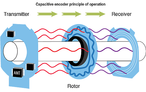
Image credit CUI Inc.
In the proprietary capacitive Electric Encoder by Netzer Precision Motion Sensors, the encoder has two operating modes: Coarse Mode and Fine Mode. Coarse Mode is typically used upon system start-up, to determine the initial position. The encoder is then switched to Fine Mode for ongoing operation. By breaking up the total measuring range into small, equal, distinct segments, the scale of each segment can be much finer than if the same scale were used over the entire measuring range. This enables very high resolution without added expense.
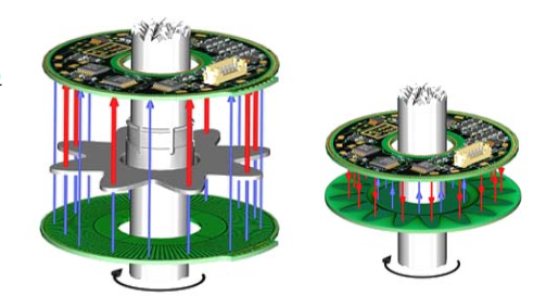
Right: A two-part capacitive encoder with a combined transmitter/receiver, and a rotor.
Image credit: Netzer Precision Motion Sensors Ltd.
The primary concern when using capacitive encoders is their susceptibility to noise and electrical interference. To combat this, the ASIC circuitry must be carefully designed and the algorithms for de-modulation must be fine-tuned. Capacitive technology, however, has been used for many decades in digital calipers and is well-proven. Now it is making its way into the encoder product space, where it provides high resolution without sacrificing robustness.
Feature image credit: CUI Inc.


Leave a Reply
You must be logged in to post a comment.