
Image credit: electrical4u.com
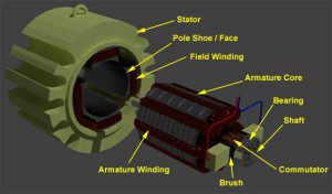
In electrical terminology, a parallel circuit is often referred to as a shunt. Hence, DC motors in which the armature and field windings are connected in parallel are referred to as DC shunt motors. The variations in construction between series-wound DC motors and DC shunt motors result in some differences in operation between the two types, but the most significant difference lies in their speed characteristics. Where a series-wound DC motor exhibits a direct, inverse relationship between load and speed, a DC shunt motor is able to maintain a constant speed, regardless of the load on the motor.
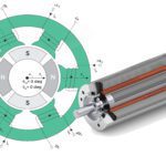
Parallel vs series windings
In a series-wound DC motor, the armature windings and field windings are connected in series and current through them is equal (Itotal = Ia = If). Because the armature windings and field windings of a DC shunt motor are connected in parallel, the current in a shunt motor is split into two parts—current through the armature and current through the field windings—and total current is the sum of the two parts.
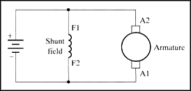
Image credit: National Instruments Corporation
![]()
Where:
Itotal = supply current
Ia = current though armature windings
Ish = current through shunt (field) windings
The shunt (field) windings of a DC shunt motor are made of smaller gauge wire, but they have many more turns than a series-wound DC motor. The high number of turns allows a strong magnetic field to be generated, but the smaller gauge wires provide a high resistance and limit the current flowing through the shunt coil. Therefore, the starting torque of a DC shunt motor is low, meaning that the shaft load must be small at startup.
In a DC shunt motor, torque is proportional to armature current (as shown in the torque equation below). In contrast, for a series-wound DC motor, torque increases as the square of armature current. This exponential torque-current relationship allows series-wound DC motors to provide high starting torque and handle high startup loads.
How DC shunt motors achieve speed regulation
When voltage is applied to a DC shunt motor, the armature draws current sufficient to produce a strong magnetic field, which interacts with the magnetic field produced by the shunt windings, causing the armature to rotate. The rotating armature (aka rotor) produces a back EMF, which opposes the armature voltage and reduces the armature current. If the load on the motor is increased, the armature rotation slows and back EMF is reduced, since back EMF is proportional to speed.
![]()
Where:
Eb = back EMF
Φ = flux
P = number of poles
Z = number of coils
N = rotational speed
With less back EMF voltage and a constant supply voltage (E), the net voltage increases.
![]()
The increase in net voltage results in an increase in armature current. Since torque is proportional to armature current, torque also increases.
![]()
Where:
T = torque
A = area
Finally, this increased torque allows the motor to increase its speed and compensate for the slowdown due to loading. Hence, a DC shunt motor is able to self-regulate its speed, and can be referred to as a constant speed motor.
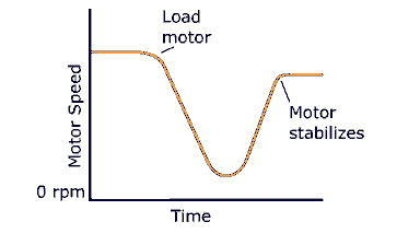
Image credit: electrical4u.com
Uses for DC shunt motors
Because of their self-regulating speed capabilities, DC shunt motors are ideal for applications where precise speed control is required. Keep in mind, however, that they cannot produce high starting torque, so the load at startup must be small. Applications that meet these criteria and are suitable for DC shunt motors include machines tool such as lathes and grinders, and industrial equipment such as fans and compressors.


Leave a Reply
You must be logged in to post a comment.