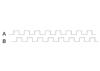
An encoder is a device that measures position, and in some configurations, can also measure direction. Rotary encoders measure rotation of a shaft, while linear encoders measure distance traveled. For both types of encoder, the position measurement can be either incremental or absolute. An incremental encoder measures change in position, but does not keep track of actual position. When power is interrupted, incremental encoders lose their position reference and must start over via a re-homing sequence to a reference point. Absolute encoders, on the other hand, keep track of absolute position, whether rotation of a shaft or linear travel, by assigning a unique digital value to each position. So even if power is lost, an absolute encoder will know the exact position of the shaft or the linear drive.
Incremental encoders work by producing a specific number of equally spaced pulses per revolution (PPR) or per distance (PPM—pulses per millimeter, or PPI—pulses per inch). When one set of pulses, or output channel, is used, the encoder can determine position only. But most incremental encoders use quadrature output, which consists of two channels, typically referred to as channel A and channel B, that are out of phase by 90 degrees. Quadrature output allows the encoder to also sense direction, by determining which channel is leading and which is following. Some incremental encoders also produce a third channel with a single pulse, commonly referred to as channel Z or channel I. This channel serves as the index or reference position for homing.
With quadrature output, three types of encoding can be used: X1, X2, or X4. The difference between these encoding types is simply which edges of which channel are counted during movement, but their influence on encoder resolution is significant.
With X1 encoding, either the rising (aka leading) or the falling (aka following) edge of channel A is counted. If channel A leads channel B, the rising edge is counted, and the movement is forward, or clockwise. Conversely, if channel B leads channel A, the falling edge is counted, and the movement is backwards, or counterclockwise.

Image credit: National Instruments Corporation
When X2 encoding is used, both the rising and falling edges of channel A are counted. This doubles the number of pulses that are counted for each rotation or linear distance, which in turn doubles the encoder’s resolution.

Image credit: National Instruments Corporation
X4 encoding goes one step further, to count both the rising and falling edges of both channels A and B, which quadruples the number of pulses and increases resolution by four times.

Image credit: National Instruments Corporation
For rotary encoders, position is calculated by dividing the number of edges counted by the product of the number of pulses per revolution and the encoding type described above (1, 2, or 4), and then multiplying the result by 360 in order to get degrees of motion.
x = type of encoding (X1, X2, or X4)
N = number of pulses generated per shaft revolution
For linear encoders, position is calculated by dividing the number of edges counted by the product of the number pulses per revolution and the encoding type. This result is then multiplied by the inverse of the pulses per millimeter (or per inch).
PPM = pulses per millimeter
PPI = pulses per inch
Incremental encoders are a relatively simple and inexpensive feedback option for applications where re-homing after a power loss is not detrimental to the process. And with quadrature output, incremental encoders can achieve high resolution, even at high speeds.

Featured image credit: National Instruments Corporation


Leave a Reply
You must be logged in to post a comment.