• Skip to primary navigation
  • Skip to main content
  • Skip to primary sidebar
  • Skip to footer

Motion Control Tips

Automation • Motion Control • Power Transmission

  • News
    • Industry News
    • Editor Blogs
    • Video
  • Controls
    • HMIs
    • PC-Based Controllers
    • PLCs + PACs
    • Stand-Alone Controllers
    • Software
  • Drives
    • Servo Drives
    • Stepper Drives
  • Encoders
    • Absolute Encoders
    • Incremental Encoders
    • Rotary Encoders
  • Mechanical
    • Bearings
    • Brakes + Clutches
    • Belt + chain
    • Couplings
    • Gears + Gearing
    • Lubrication
    • Shock + Vibration Mitigation
    • Springs + Rings + Seals
  • Linear
    • Actuators
    • Linear Motors
    • Linear Encoders
  • Motors
    • AC Motors
    • DC Motors
    • Brushless Motors
    • Gearmotors
    • Piezo Motors
    • Servo Motors
    • Stepper Motors
  • Systems
    • Conveyors + linear transport systems
    • Gantries + Stages
    • Rotary Tables
    • Grippers + End Effectors
    • Robotics
  • Networks
    • Connections + Sliprings
    • Fieldbuses
    • I/O
    • Sensors + Vision
  • FAQs
    • Motion Casebook
    • Motion Selection Guides
  • Suppliers
You are here: Home / Motors / DC Motors / The relationship between voltage and dc motor output speed

The relationship between voltage and dc motor output speed

December 6, 2015 By Danielle Collins Leave a Comment

The operation of a DC motor is relatively straightforward. A coil is placed in a magnetic field, and when an electric current passes through the coil, a torque is produced, causing the motor to turn. The entire process is driven by applying electrical power to the coil, with the source voltage having a direct relationship to the motor’s output speed. To understand this relationship between voltage and speed, let’s look at a typical brushed dc motor circuit.

DC motor
DC motor circuit. Image credit: Precision Microdrives Ltd.

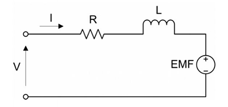
The applied voltage equals the voltage drop across the coil resistance, R, and the inductor, L, plus the back-EMF.

DC motor

Where:

V = applied voltage

I = current

R = resistance

L = inductance

E = back-EMF

The voltage equation can be simplified by assuming that the current is constant, in which case inductance can be disregarded:

DC motor

The back-EMF (electromotive force) is a voltage that is generated by the rotation of the coil. It opposes the applied voltage, reducing the voltage flowing through the motor.  Back-EMF is calculated as:

DC motor

Where:

kE = electrical constant, inherent to the motor

ω = angular velocity of the motor

Substituting for E in the voltage equation, we get:

DC motor

The current, I, through the motor coil is directly related to the motor’s torque:

DC motor

Which can be rearranged as:

DC motor

Where:

T = torque

kT = torque constant, inherent to the motor

Substituting for I, the voltage equation now becomes:

DC motor

This shows the direct relationship between the applied voltage and the motor’s angular velocity. Rearranging to solve for the angular velocity:

DC motor

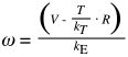
For DC motors, the torque and electrical constants, kT and kE, are equal, so the angular velocity equation can be simplified to:

DC motor

From this we can see that the motor’s maximum speed occurs when there’s no load (torque) on the motor.

Rearranging for torque:

DC motor

Similarly, maximum torque occurs when angular velocity is zero.

These two relationships can be seen in a typical DC motor’s torque-speed curve.

DC motor
DC motor torque-speed curve
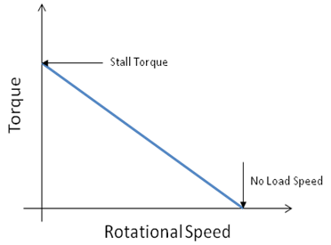
Image credit: National Instruments Corporation

Back to the original question:  how does voltage affect speed? From the analysis above, we can see that when the load (torque) on the motor is constant, speed is directly proportional to supply voltage. And, when the voltage remains constant, an increase in the load (torque) on the motor results in a decrease in speed.

Feature image credit: MICROMO

Filed Under: DC Motors, FAQs + basics, Motors Tagged With: DC motor, motor, speed

Reader Interactions

Leave a Reply

You must be logged in to post a comment.

Primary Sidebar

POWER TRANSMISSION REFERENCE GUIDE

DESIGN GUIDE LIBRARY

“motion
Subscribe Today

RSS Featured White Papers

  • Specifying electric rodless actuators: Ten tips for maximizing actuator life and system performance
  • The truth about actuator life: Screw drive survival
  • Top Ten Tips: How to specify electric rod-style actuators for optimal performance, reliability and efficiency

Footer

Motion Control Tips

DESIGN WORLD NETWORK

Design World Online
The Robot Report
Coupling Tips
Linear Motion Tips
Bearing Tips
Fastener Engineering.

MOTION CONTROL TIPS

Subscribe to our newsletter
Advertise with us
Contact us
About us
Follow us on TwitterAdd us on FacebookAdd us on LinkedInAdd us on YouTubeAdd us on Instagram

Copyright © 2022 · WTWH Media LLC and its licensors. All rights reserved.
The material on this site may not be reproduced, distributed, transmitted, cached or otherwise used, except with the prior written permission of WTWH Media.

Privacy Policy | RSS