• Skip to primary navigation
  • Skip to main content
  • Skip to primary sidebar
  • Skip to footer

Motion Control Tips

Automation • Motion Control • Power Transmission

  • News
    • Industry News
    • Editor Blogs
    • Video
  • Controls
    • HMIs
    • PC-Based Controllers
    • PLCs + PACs
    • Stand-Alone Controllers
    • Software
  • Drives
    • Servo Drives
    • Stepper Drives
  • Encoders
    • Absolute Encoders
    • Incremental Encoders
    • Rotary Encoders
  • Mechanical
    • Bearings
    • Brakes + Clutches
    • Belt + chain
    • Couplings
    • Gears + Gearing
    • Lubrication
    • Shock + Vibration Mitigation
    • Springs + Rings + Seals
  • Linear
    • Actuators
    • Linear Motors
    • Linear Encoders
  • Motors
    • AC Motors
    • DC Motors
    • Brushless Motors
    • Gearmotors
    • Piezo Motors
    • Servo Motors
    • Stepper Motors
  • Systems
    • Conveyors + linear transport systems
    • Gantries + Stages
    • Rotary Tables
    • Grippers + End Effectors
    • Robotics
  • Networks
    • Connections + Sliprings
    • Fieldbuses
    • I/O
    • Sensors + Vision
  • FAQs
    • Motion Casebook
    • Motion Selection Guides
  • Suppliers
You are here: Home / Motors / DC Motors / What’s the relationship between current and dc motor output torque?

What’s the relationship between current and dc motor output torque?

December 23, 2015 By Danielle Collins Leave a Comment

Torque is a rotational force produced when a vertical force is applied at some distance from the center axis of the rotating body. The familiar equation for torque is:

DC motor

Where:

T = torque

F = applied vertical force

d = distance from axis of rotation

In a DC motor, the output torque is directly proportional to the current through the windings, and is given as:

DC motor

Where:

I = current through the windings

kT = torque constant (specific to the motor)

To see how this relationship is developed, let’s look at the geometry of a DC motor:

DC Motor
A 4-pole DC motor
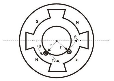
Image credit: electrical4u.com

The force on one coil is the product of flux density, current through the coil, and the length of the coil:

DC Motor

Where:

Fc = force on one coil

B = flux density

Ic = current through one coil

L = length of the coil

The current through one coil is calculated as:

DC motor

Where:

Ia = total current through the armature

A = area of the coil

Substituting for Ic in the force equation, we get:

DC motor

Because torque equals force times distance, the torque equation can be shown as:

DC motor

Where:

Tc = torque on one coil

r = distance from center of armature

The flux density, B, equals the total flux divided by area:

DC motor

Where:

φ = total flux

Because the motor is essentially a cylinder, area is calculated as:

DC motor

Where:

P = number of poles

Substituting into the flux density equation, we get:

DC motor

Substituting this into the torque equation, we get:

DC motor

Which simplifies to:

DC motor

Tc is the torque on just one coil. Total torque equals Tc multiplied by the number of coils:

DC motor

Where:

T = total torque

Z = number of coils

To further simplify the torque equation, the number of poles (P), the number of coils (Z), and the geometric factors (2πA) can be combined to form the torque constant, kT, which is specific to the motor.  This simplifies the torque equation to:

DC motor

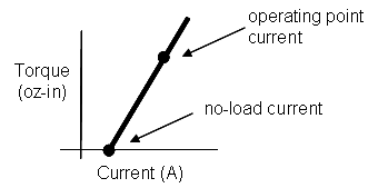
For most DC motor cases, we can assume the flux, φ, is constant, making torque directly proportional to the current:

DC motor

When examining the torque-current curve for a DC motor, notice that the no-load (stall) current is greater than zero. This is because some current is needed to overcome the internal friction of the motor.

DC motor
Torque-current curve for a DC motor.

Filed Under: DC Motors, FAQs + basics, Motors Tagged With: current, DC motor, torque, torque calculation

Reader Interactions

Leave a Reply Cancel reply

You must be logged in to post a comment.

Primary Sidebar

MOTION DESIGN GUIDES

“motion

“motion

“motion

“motion

“motion

POWER TRANSMISSION REFERENCE GUIDE

RSS Linear Motion Tips

  • Haydon Kerk Pittman launches compact Z-Theta motion platform
  • Three easy ways to specify application requirements for linear motion systems
  • Sourcing linear motion solutions from NSK’s global manufacturing sites
  • Ride the wave of electrification: Off-highway designs with linear actuators
  • What are capacitive sensors and where are they used?
Subscribe Today

RSS Featured White Papers

  • Identifying Best-Value Linear Motion Technologies
  • Learn how to reduce noise and distortion in encoders’ signals
  • Helical Planetary Gearboxes: Understanding The Tradeoffs
Tweets from https://twitter.com/Motion_Control/lists/motion-control-tweets

Footer

Motion Control Tips

DESIGN WORLD NETWORK

Design World Online
The Robot Report
Coupling Tips
Linear Motion Tips
Bearing Tips
Fastener Engineering

MOTION CONTROL TIPS

Subscribe to our newsletter
Advertise with us
Contact us
About us
Follow us on TwitterAdd us on FacebookAdd us on LinkedInAdd us on YouTubeAdd us on Instagram

Copyright © 2021 · WTWH Media LLC and its licensors. All rights reserved.
The material on this site may not be reproduced, distributed, transmitted, cached or otherwise used, except with the prior written permission of WTWH Media.

Privacy Policy | RSS