
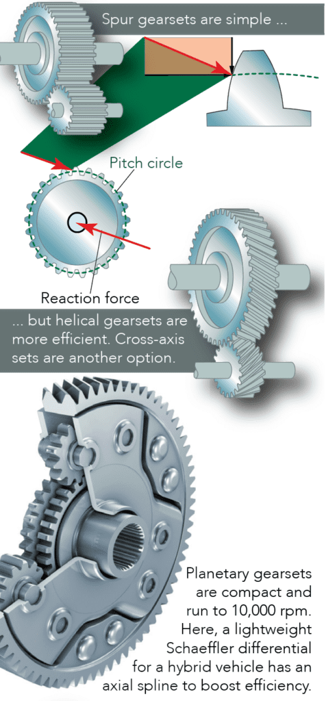
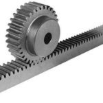
Helical gears and spur gears are two of the most common gear types and can be used in many of the same applications. Spur gears are simple and inexpensive to manufacture, but helical gears offer some important advantages over spur gears.
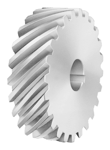
The teeth of a helical gear are set at an angle (relative to axis of the gear) and take the shape of a helix. This allows the teeth to mesh gradually, starting as point contact and developing into line contact as engagement progresses. One of the most noticeable benefits of helical gears over spur gears is less noise, especially at medium- to high-speeds. Also, with helical gears, multiple teeth are always in mesh, which means less load on each individual tooth. This results in a smoother transition of forces from one tooth to the next, so that vibrations, shock loads, and wear are reduced.
But the inclined angle of the teeth also causes sliding contact between the teeth, which produces axial forces and heat, decreasing efficiency. These axial forces play a significant role in bearing selection for helical gears. Because the bearings have to withstand both radial and axial forces, helical gears require thrust or roller bearings, which are typically larger (and more expensive) than the simple bearings used with spur gears. The axial forces vary in proportion to the magnitude of the tangent of the helix angle. Although larger helix angles provide higher speed and smoother motion, the helix angle is typically limited to 45 degrees due to the production of axial forces.
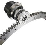
The axial loads produced by helical gears can be countered by using double helical or herringbone gears. These arrangements have the appearance of two helical gears with opposite hands mounted back-to-back, although in reality they are machined from the same gear. (The difference between the two designs is that double helical gears have a groove in the middle, between the teeth, whereas herringbone gears do not.) This arrangement cancels out the axial forces on each set of teeth, so larger helix angles can be used. It also eliminates the need for thrust bearings.
Besides smoother motion, higher speed capability, and less noise, another advantage that helical gears provide over spur gears is the ability to be used with either parallel or non-parallel (crossed) shafts. Helical gears with parallel shafts require the same helix angle, but opposite hands (i.e. right-handed teeth vs. left-handed teeth).
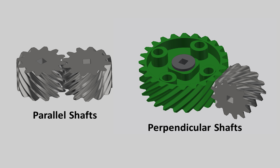
When crossed helical gears are used, they can be of either the same or opposite hands. If the gears have the same hands, the sum of the helix angles should equal the angle between the shafts. The most common example of this are crossed helical gears with perpendicular (i.e. 90 degree) shafts. Both gears have the same hand, and the sum of their helix angles equals 90 degrees. For configurations with opposite hands, the difference between helix angles should equal the angle between the shafts. Crossed helical gears provide flexibility in design, but the contact between teeth is closer to point contact than line contact, so they have lower force capabilities than parallel shaft designs.
Helical gears are often the default choice in applications that are suitable for spur gears but have non-parallel shafts. They are also used in applications that require high speeds or high loading. Regardless of the load or speed, they generally provide smoother, quieter operation than spur gears.


Leave a Reply
You must be logged in to post a comment.