• Skip to primary navigation
  • Skip to main content
  • Skip to primary sidebar
  • Skip to footer

Motion Control Tips

Automation • Motion Control • Power Transmission

  • News
    • Industry News
    • Editor Blogs
    • Video
  • Controls
    • HMIs
    • PC-Based Controllers
    • PLCs + PACs
    • Stand-Alone Controllers
    • Software
  • Drives
    • Servo Drives
    • Stepper Drives
  • Encoders
    • Absolute Encoders
    • Incremental Encoders
    • Rotary Encoders
  • Mechanical
    • Bearings
    • Brakes + Clutches
    • Belt + chain
    • Couplings
    • Gears + Gearing
    • Lubrication
    • Shock + Vibration Mitigation
    • Springs + Rings + Seals
  • Linear
    • Actuators
    • Linear Motors
    • Linear Encoders
  • Motors
    • AC Motors
    • DC Motors
    • Brushless Motors
    • Gearmotors
    • Piezo Motors
    • Servo Motors
    • Stepper Motors
  • Systems
    • Conveyors + linear transport systems
    • Gantries + Stages
    • Rotary Tables
    • Grippers + End Effectors
    • Robotics
  • Networks
    • Connections + Sliprings
    • Fieldbuses
    • I/O
    • Sensors + Vision
  • FAQs
    • Motion Casebook
    • Motion Selection Guides
  • Suppliers
You are here: Home / FAQs + basics / How can a universal motor operate on either DC or AC supply?

How can a universal motor operate on either DC or AC supply?

May 15, 2018 By Danielle Collins Leave a Comment

A universal motor is a series-wound motor — meaning that the field and armature windings are connected in series — and is mechanically commutated with brushes and a commutator. Although its construction is very similar to a series-wound DC motor, a universal motor incorporates several modifications that allow it operate properly on either DC or AC power supply.


universal motor
For proper operation with AC supply, a universal motor incorporates a compensation winding, in series with the armature and field winding.
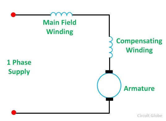
Image credit: circuitglobe.com

When the motor runs on AC voltage, the alternating flux causes a reactance voltage, which limits the current to a much lower level than would be produced with DC voltage. To limit the effects of this armature reaction, the universal motor uses a compensation winding, which is installed in the slots of the stator, 90 degrees electrical from the main field winding and connected in series with the armature and field winding. (This arrangement is referred to as “conductively compensated.”) The current flowing in each coil of the compensating winding is in a direction opposite to the current in the corresponding armature loop near it. The winding of equal coils in opposite directions produces a cancelling effect that reduces inductance, and therefore, reactance.

AC supply also induces more significant eddy currents than are produced when the motor operates on DC supply. To curtail eddy current losses, universal motors use laminated cores (rather than solid iron), which increases their resistance and reduces eddy currents.


Armature reaction is the interference of the main field flux caused by the armature flux. This distortion and weakening of the main field flux changes the location of the magnetic neutral plane, which is the axis along which the brushes should be placed.

universal motor
Armature reaction changes the location of the magnetic neutral plane, which is the axis along which the brushes should be mounted.
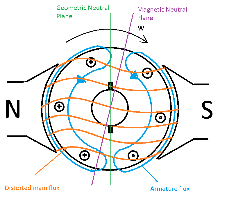
Image credit: Precision Microdrives Limited

It is because the armature and field windings are connected in series that a universal motor can operate with either DC or AC supply. Being connected in series means that both windings are supplied by the same source, so if the voltage source changes polarity, as it does with AC supply, both the armature and field currents also change polarity and the direction of torque does not change. (The direction of rotation is reversed by reversing the current in the field circuit.)

universal motor
To reduce inductance in the armature, the current flowing in each coil of the compensating winding is in a direction opposite to the current in the corresponding armature loop near it.
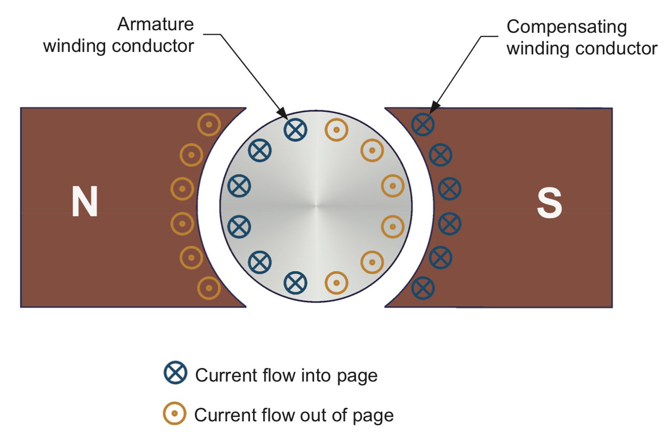
Image credit: Festo Didactic

One of the primary benefits of a universal motor is its ability to achieve (theoretically) unlimited speed, with speeds up to 20,000 rpm in real-world applications. The speed-torque curve is essentially a straight line between stall torque (zero speed) and no-load speed (zero torque), meaning that as the load (torque) increases, the speed decreases. In fact, like a series-wound DC motor, running a universal motor with no load (zero torque) could lead to a runaway condition, where the speed increases until the motor begins to break apart. The converse of this phenomenon is that universal motors produce very good starting torque (high torque at low speeds).

universal motor
A universal motor can produce extremely high speed at zero torque, but speed drops rapidly as torque increases.
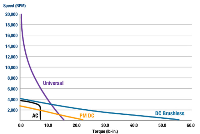
Image credit: Groschopp, Inc.

This ability to run at very high speeds means that universal motors are good for applications that involve rapidly spinning components, such as fans, blow dryers, and vacuum cleaners. And their ability to produce high torque at low speeds makes them suitable for applications such as blenders and portable drills. Because they’re mechanically commutated, universal motors generally aren’t suitable for continuous-duty applications, due to brush maintenance and wear. The brushes also make them relatively noisy, so their primary areas of application are small consumer appliances.

Feature image credit: Groschopp, Inc.

You may also like:


  • Three things to consider when selecting a customized DC motor…
  • motor starters
    FAQ: Why are starters used with DC motors?

  • Best DC motors for high starting torque?

  • FAQ: Where do brush DC motors still make sense?
  • FAULHABER-Brushless-DC-Servomotors
    What are dc motors and how do definitions vary? Technical…

Filed Under: AC Motors, DC Motors, FAQs + basics, Featured, Motors

Reader Interactions

Leave a Reply Cancel reply

You must be logged in to post a comment.

Primary Sidebar

MOTION DESIGN GUIDES

“motion

“motion

“motion

“motion

“motion

POWER TRANSMISSION REFERENCE GUIDE

RSS Linear Motion Tips

  • Haydon Kerk Pittman launches compact Z-Theta motion platform
  • Three easy ways to specify application requirements for linear motion systems
  • Sourcing linear motion solutions from NSK’s global manufacturing sites
  • Ride the wave of electrification: Off-highway designs with linear actuators
  • What are capacitive sensors and where are they used?
Subscribe Today

RSS Featured White Papers

  • Identifying Best-Value Linear Motion Technologies
  • Learn how to reduce noise and distortion in encoders’ signals
  • Helical Planetary Gearboxes: Understanding The Tradeoffs
Tweets from https://twitter.com/Motion_Control/lists/motion-control-tweets

Footer

Motion Control Tips

DESIGN WORLD NETWORK

Design World Online
The Robot Report
Coupling Tips
Linear Motion Tips
Bearing Tips
Fastener Engineering

MOTION CONTROL TIPS

Subscribe to our newsletter
Advertise with us
Contact us
About us
Follow us on TwitterAdd us on FacebookAdd us on LinkedInAdd us on YouTubeAdd us on Instagram

Copyright © 2021 · WTWH Media LLC and its licensors. All rights reserved.
The material on this site may not be reproduced, distributed, transmitted, cached or otherwise used, except with the prior written permission of WTWH Media.

Privacy Policy | RSS